Training Platform
The following code is the LabVIEW project for the VMX Training Platform.
With the project created and the project connected to the VMX, code can now be written.
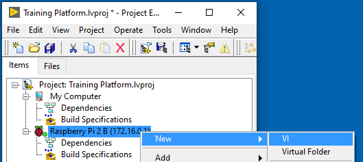
Creating the Main vi
Right click on the Raspberry Pi 2 B (172.16.0.1) target and select New -> VI
Two new windows will pop up, Front Panel and Block Diagram.
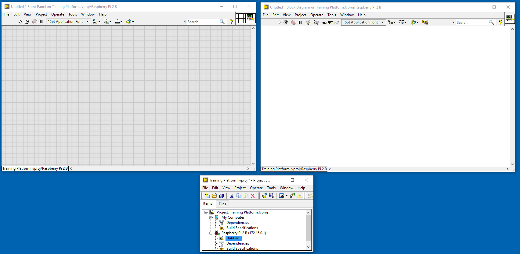
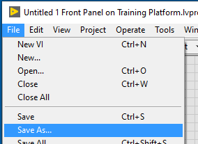
On the Front Panel (Grey window), hit File -> Save As and save the vi as Main.vi
Adding Titan Code
Referring back to the Titan Code to move the motor in the toolkit docs page. Adding the code for M1 on the Titan should be very simple.
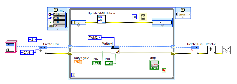
Note
In the docs page for the toolkit, we use M0, but here it needs to be changed to M1.
Adding Servo Code
Referring to the Servo Code to move the servo in the toolkit docs page, the code can be added to our motor code easily.
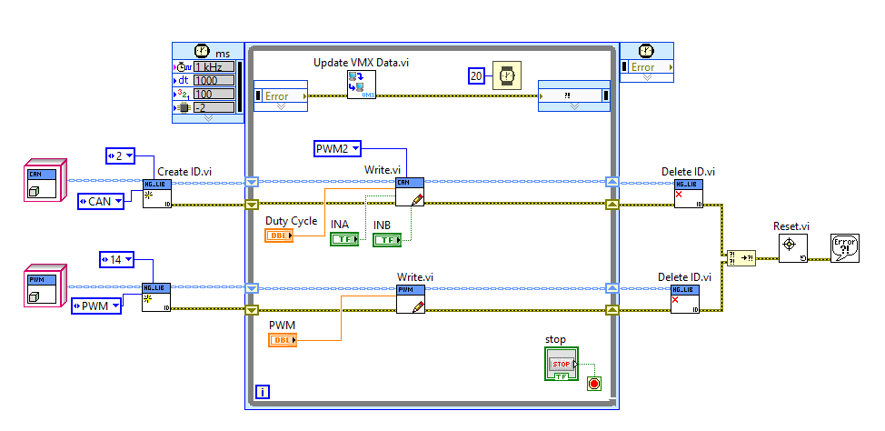
The servo will be connected to digital port 14.
Adding Sharp IR Code
Referring to the Analog Input Code to read the Sharp IR Sensor in the toolkit docs page, the code can be added.
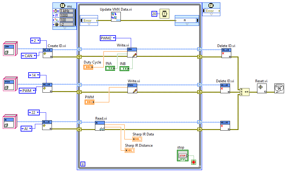
The Sharp IR sensor will be on port 22 of the VMX.
Adding Ultrasonic Code
Referring back to the Pulse Code & ISQ Code to read the Ultrasonic Sensor in the toolkit docs page, the code can be added.
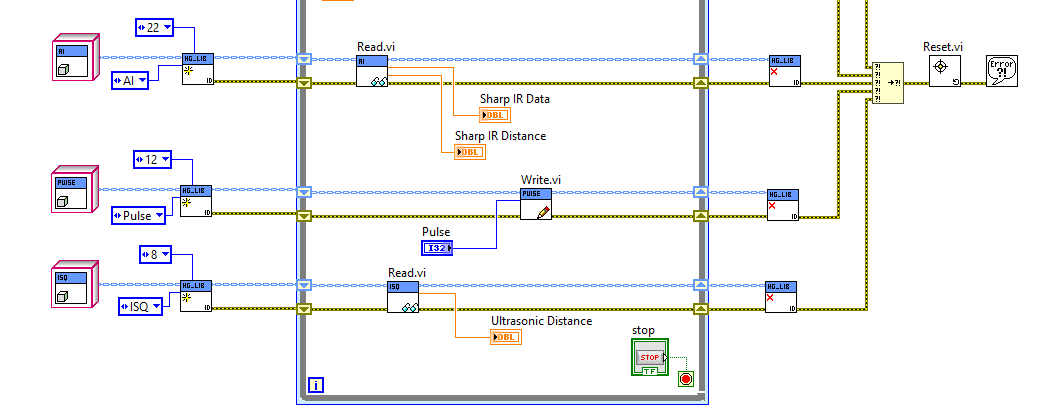
The Ultrasonic sensor will use digital port 12 for the pulse and digital port 8 for the echo.
Add Cobra Code
Referring back to the IIC Code for the Cobra, the values can be easily read.
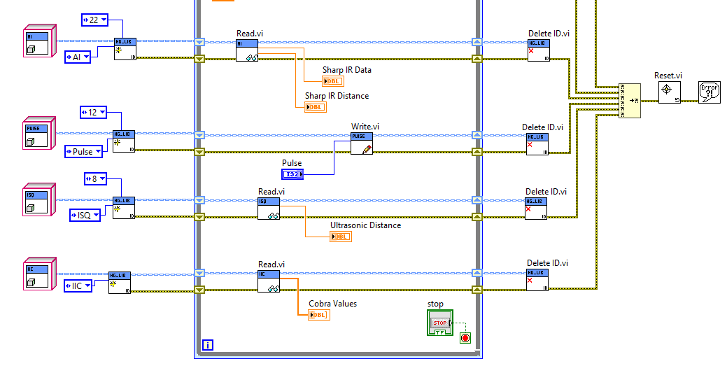
The Cobra is plugged into the ADC, which is plugged into the IIC port on the VMX.
Adding NavX Code
Referring back to the IMU Code for the internal NavX, the values can be easily read.
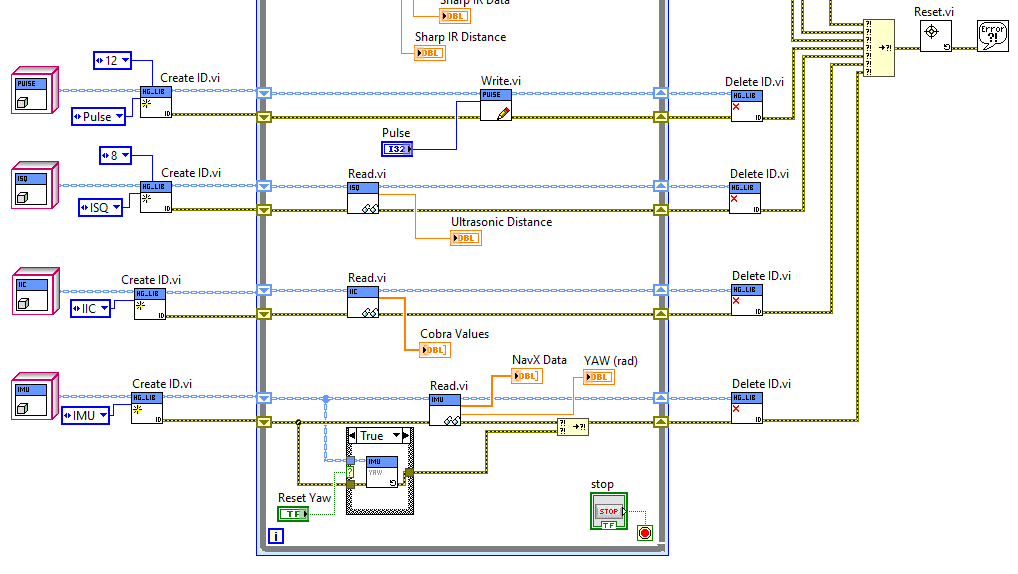
The NavX is internal and requires no wire connection.
Adding an LED Output
Referring back to the Digital Output Code an LED can be turned on.
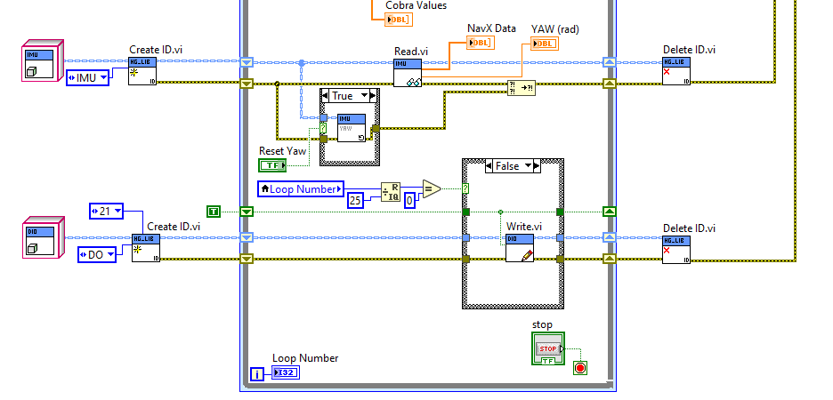
For this example, the loop counter will be used to turn the light on digital port 21 on and off every 500 ms.
Adding a Digital Input
Referring back to the Digital Input Code a push button can be read.
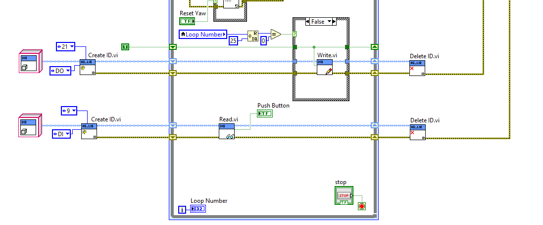
Here a pushbutton in a Normally Open configuration is used to turn an indicator on the front panel on and off.
Note
The VMX has internal pullups for inputs.
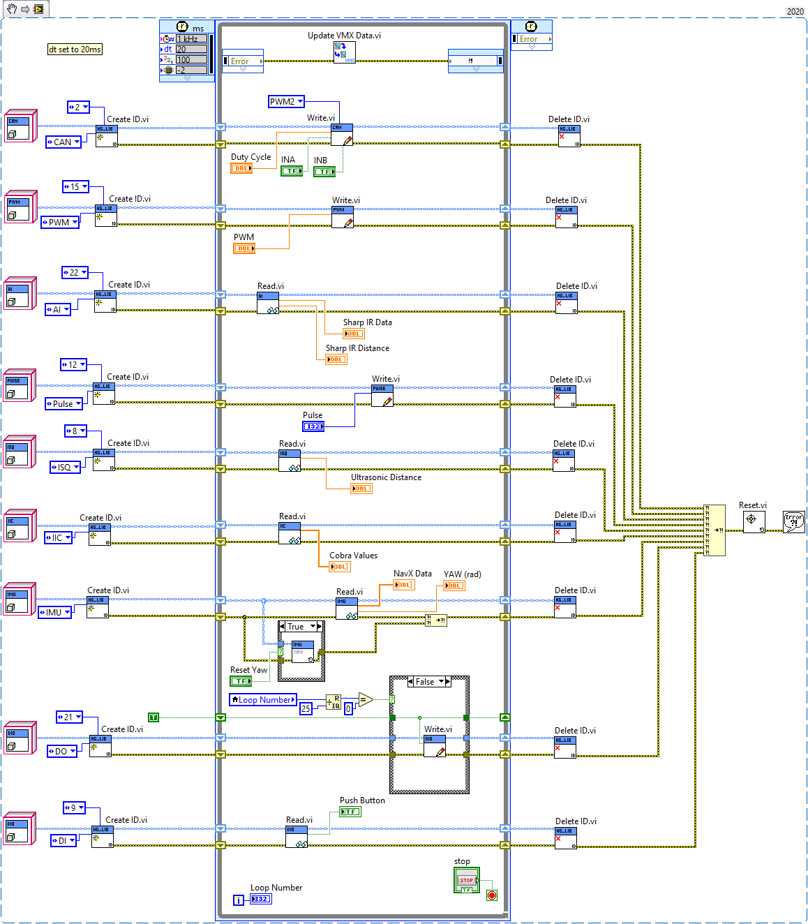
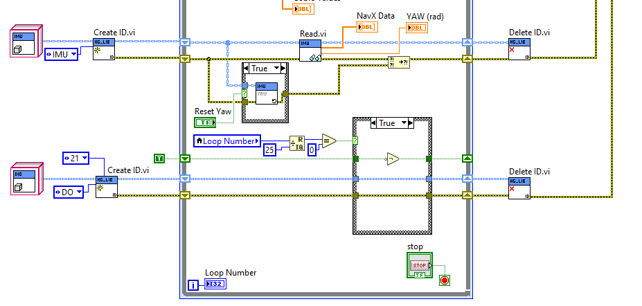
Full Code Example
Below is all the code above in one image that can be dragged into LabVIEW.
Note
The image might have to be saved first then dragged in.