Installing the Ribbon Cable
There are a few steps required to install the ribbon cable to communicate with the SR Pro camera.
Important
Take your time while completing this tutorial as the ribbon cable is fragile.
Setup
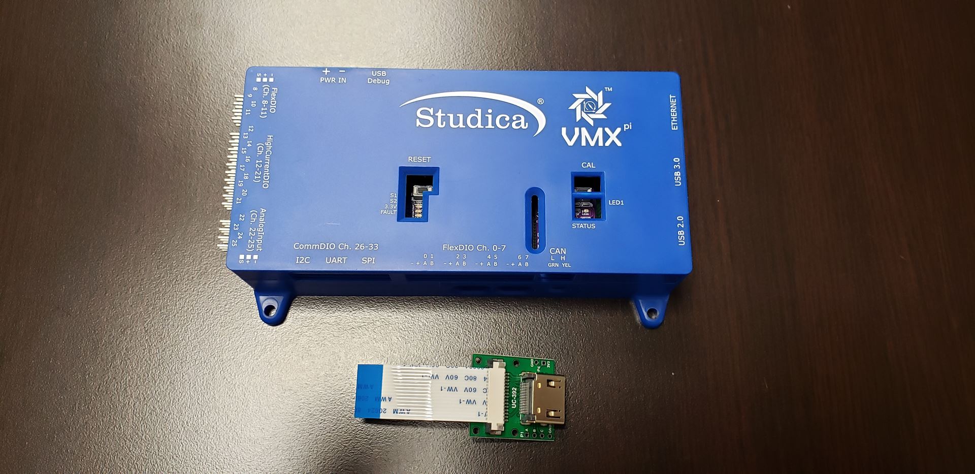
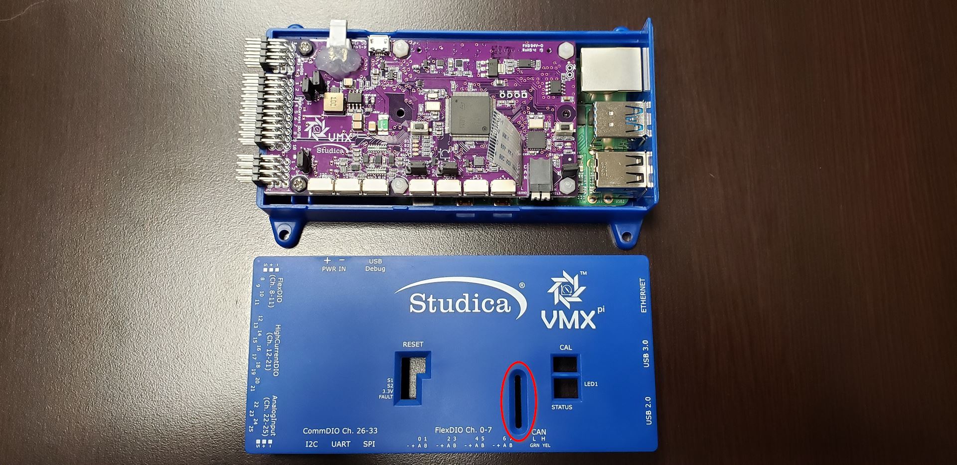
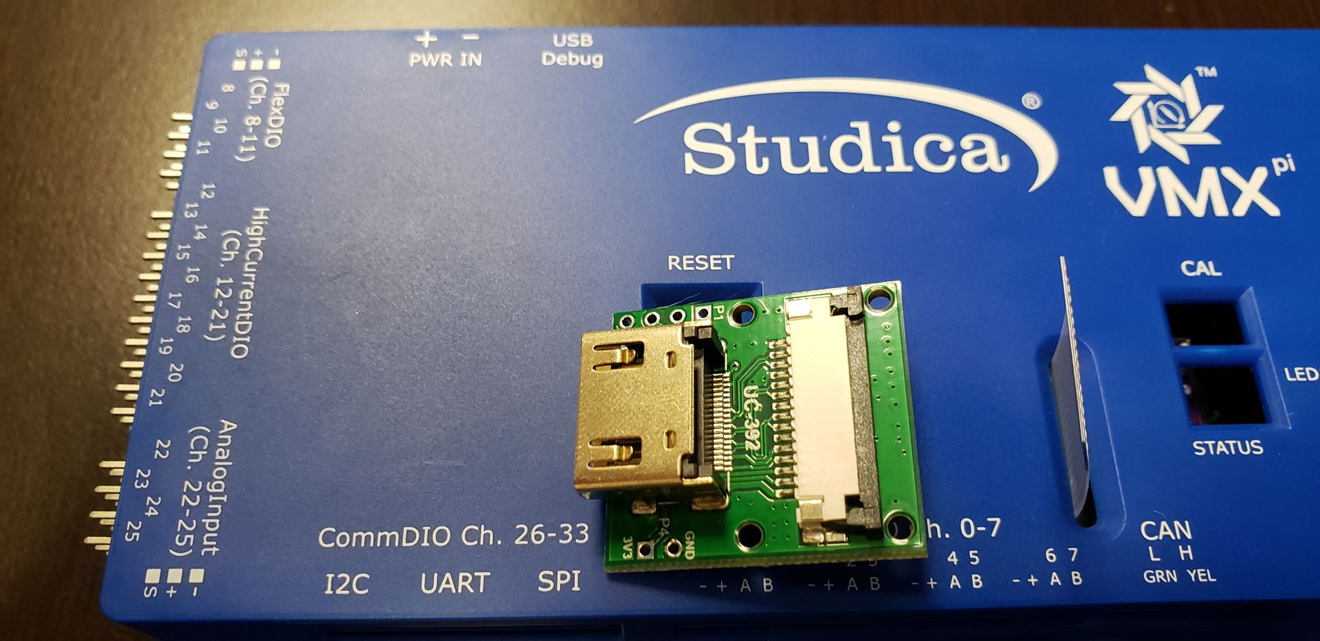
The first thing is to have the VMX and HDMI to ribbon cable adapter ready, as pictured above.
Removing the Ribbon Cable from the HDMI Adapter
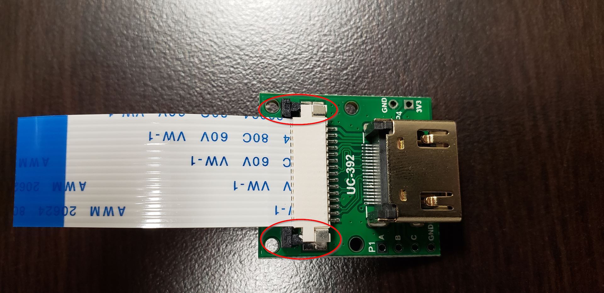
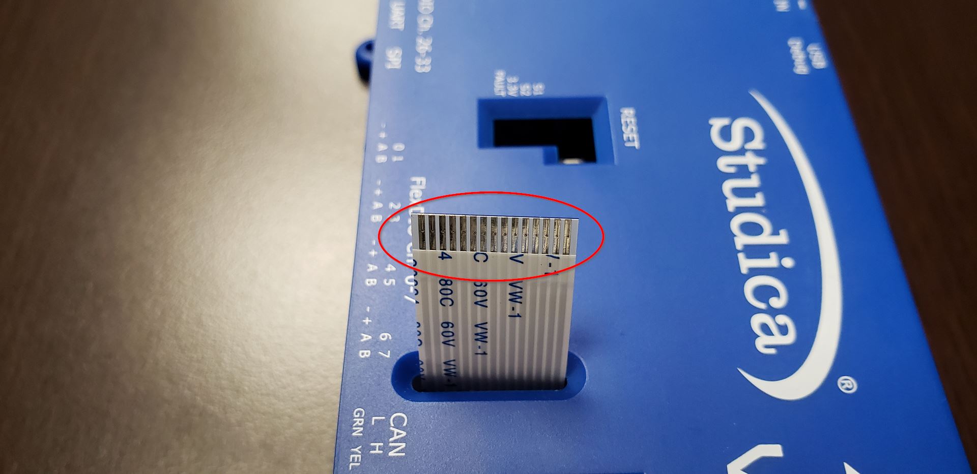
The CSI holder needs to be opened up to remove the ribbon cable from the HDMI adapter board. As highlighted above with the red circles, the ribbon cable is held down by a tab that needs to be opened. Gently pull the tab open on either end to open the CSI holder.

The ribbon cable should now be able to gently be removed.
Removing the screws from the VMX
Six M2.5 x 8mm Philips head screws hold the VMX together. All six screws need to be removed to service the VMX.
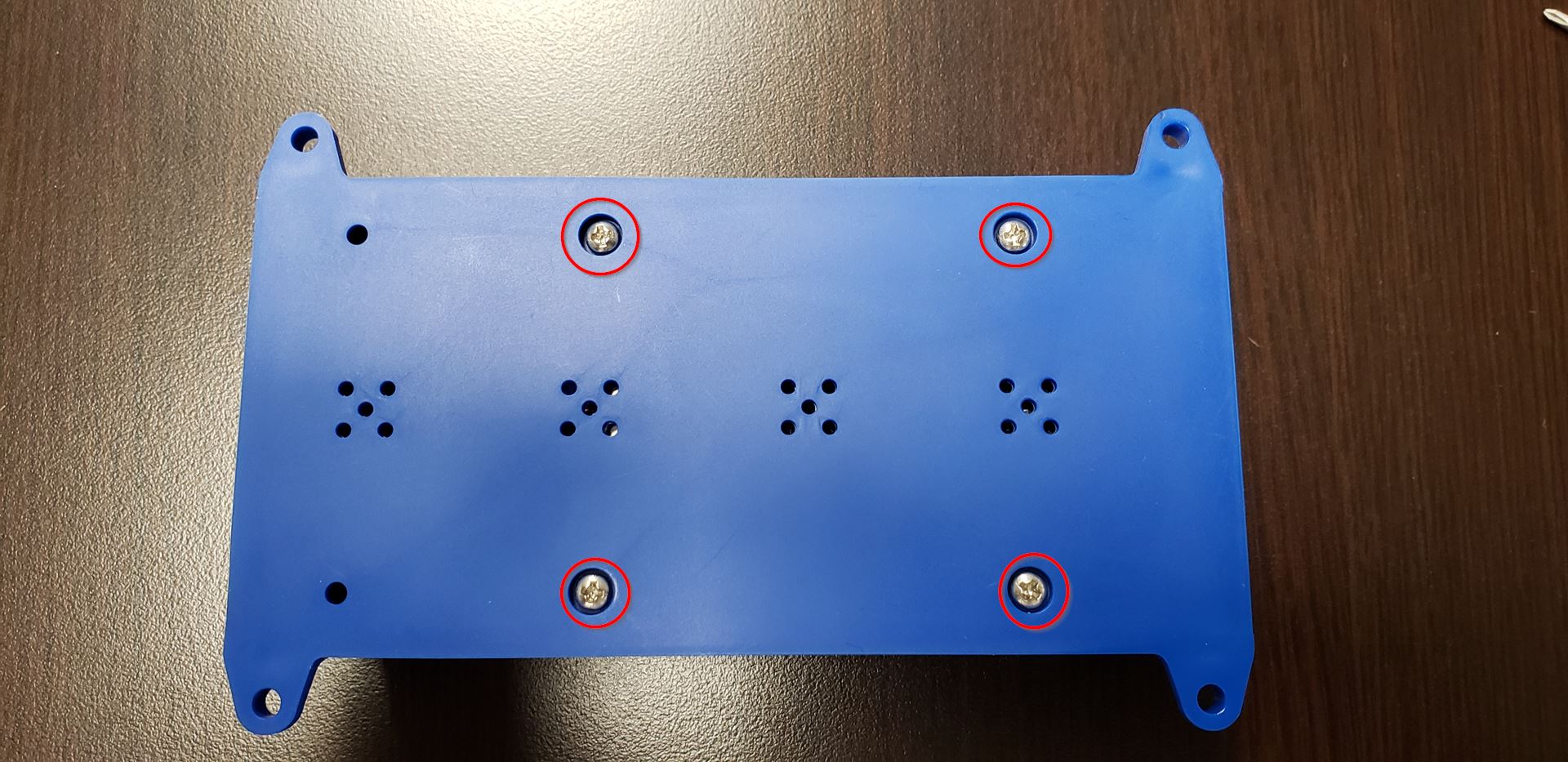
To start, flip the VMX over and remove the four screws located on the bottom of the VMX, as shown above.
Important
Place the screws in a safe spot where they won’t get lost.
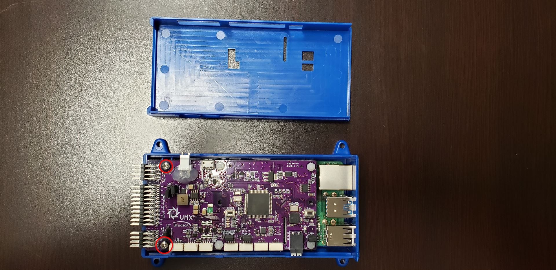
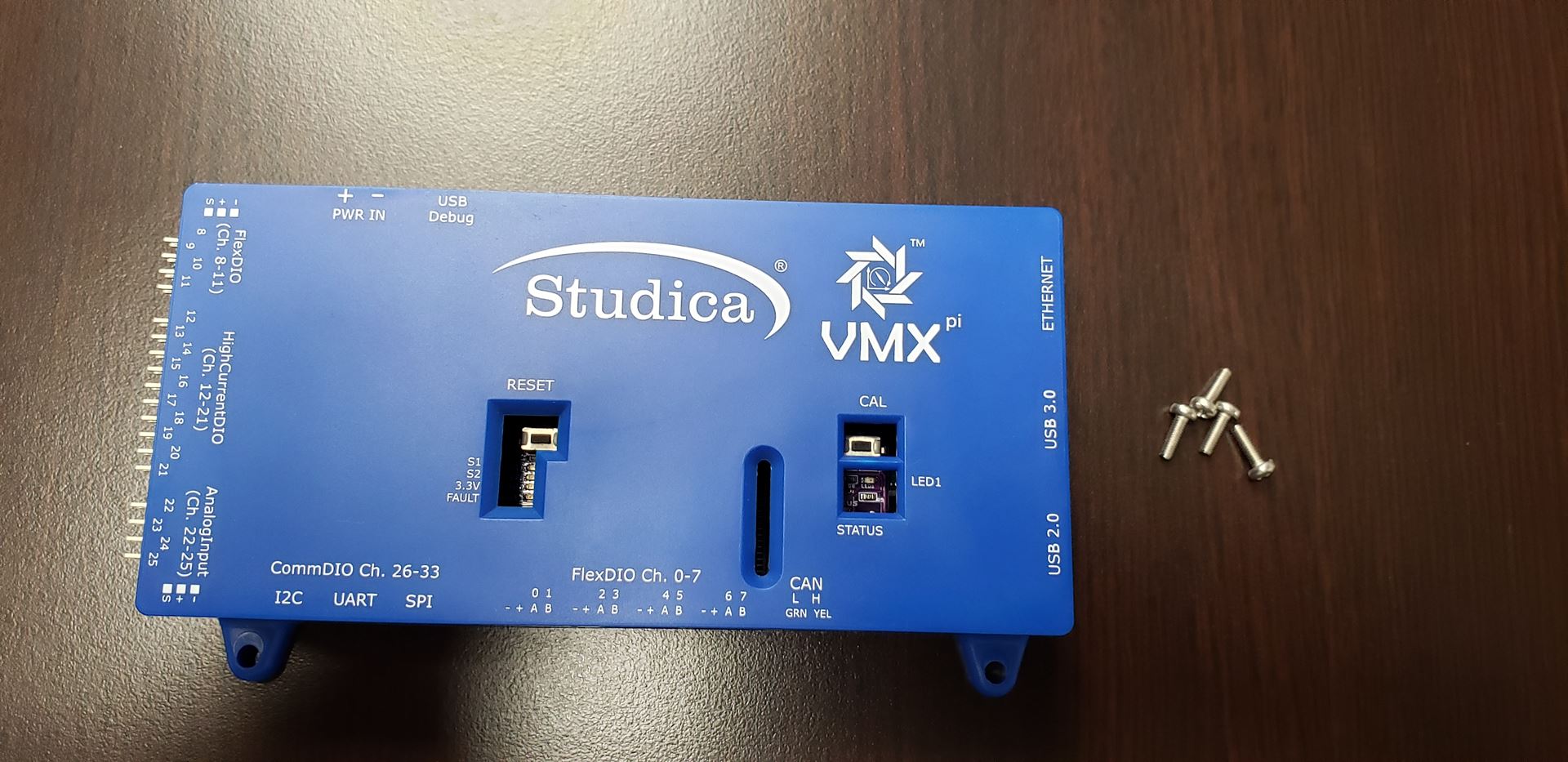
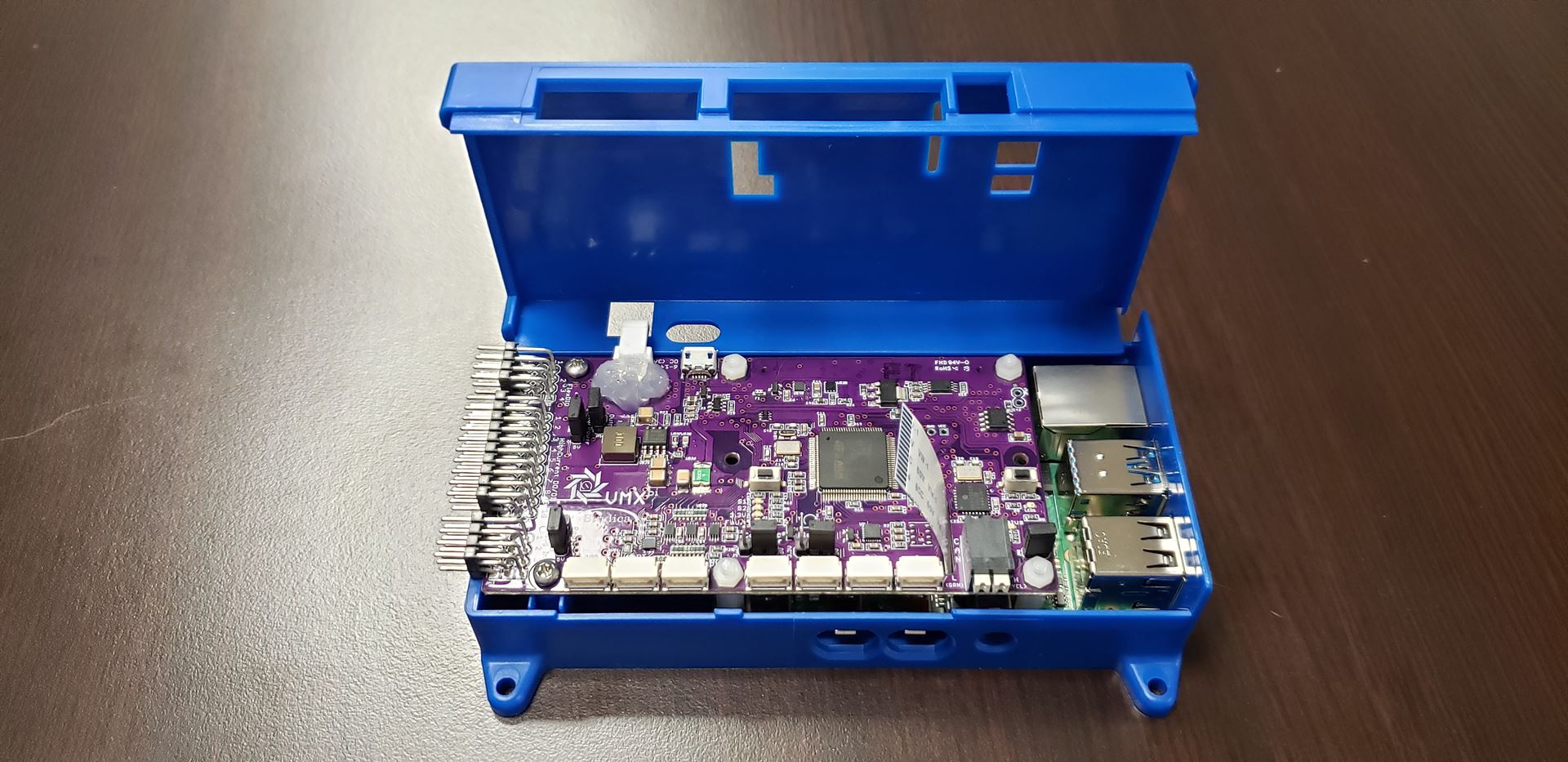
The last two screws are located inside the VMX next to the IO headers (highlighted above). To access the inside, remove the lid of the VMX and set it aside.
The VMX can now be removed from the case.
Disassembling the VMX Boards
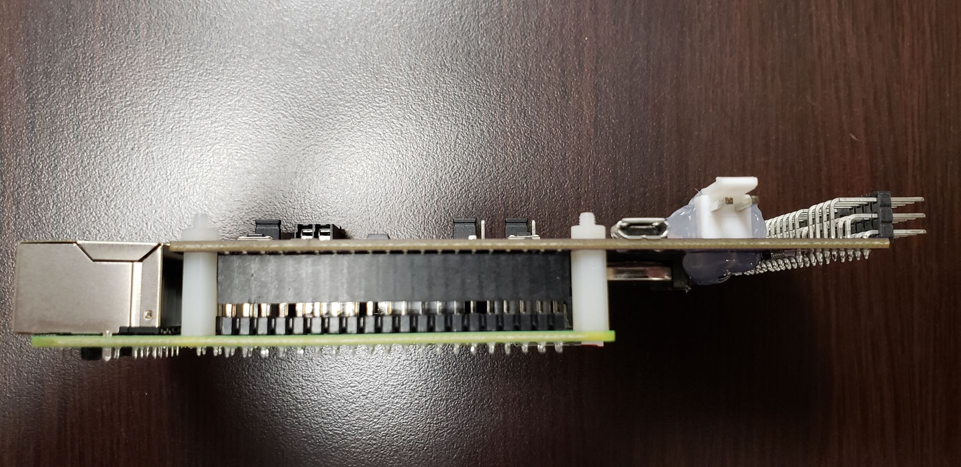
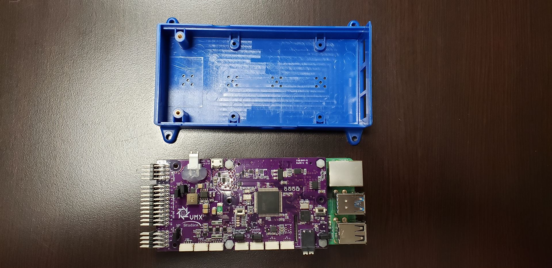
The VMX consists of two boards, the VMX-pi and the Raspberry Pi4 B+. The two boards are separated by a 12mm standoff and a GPIO header, as pictured above. Gently separate the two boards to get access to the Raspberry Pi.
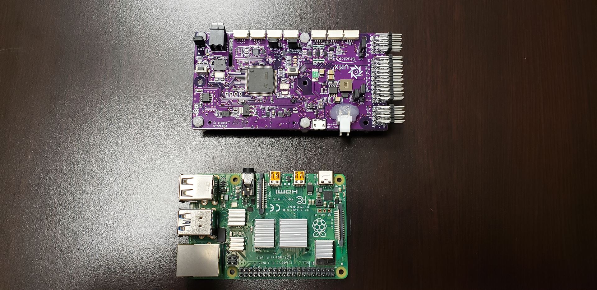
The two boards separated are shown above.
Plugging in the Ribbon Cable
The ribbon cable will sit inside the Raspberry Pi camera CSI connector.
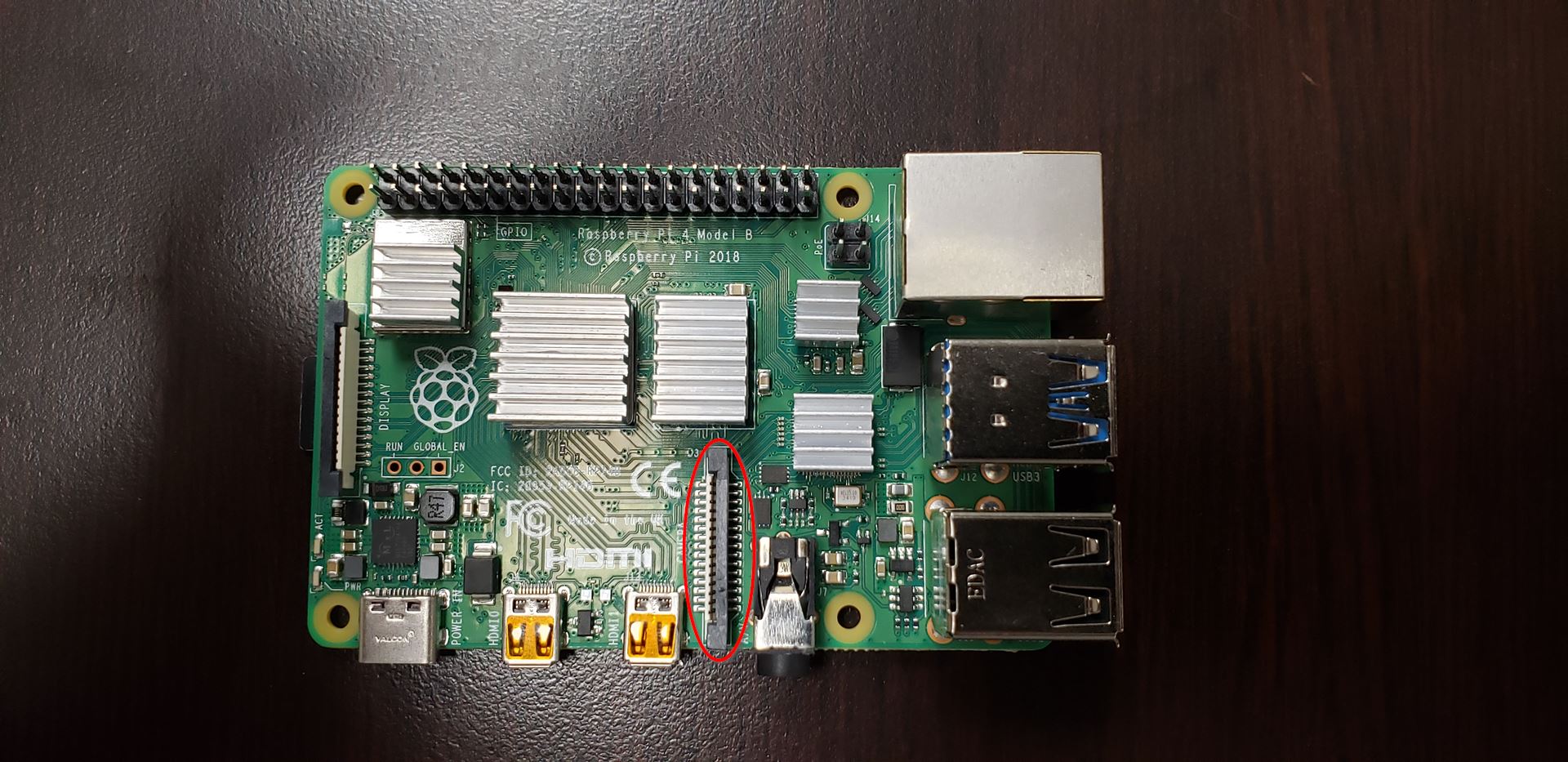
The CSI connector on the Raspberry Pi is highlighted above.
Note
Do not use the other CSI connector on the Raspberry Pi as that is for display output.
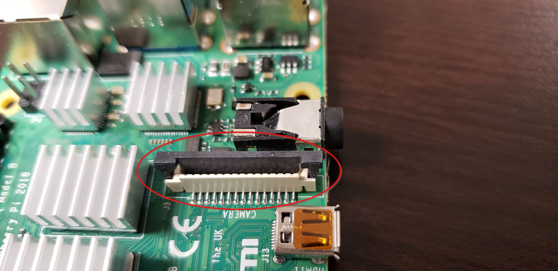
Open the CSI connector, as shown above. If the CSI connector is closed, the ribbon cable will not be able to be seated.
When open, insert the ribbon cable.
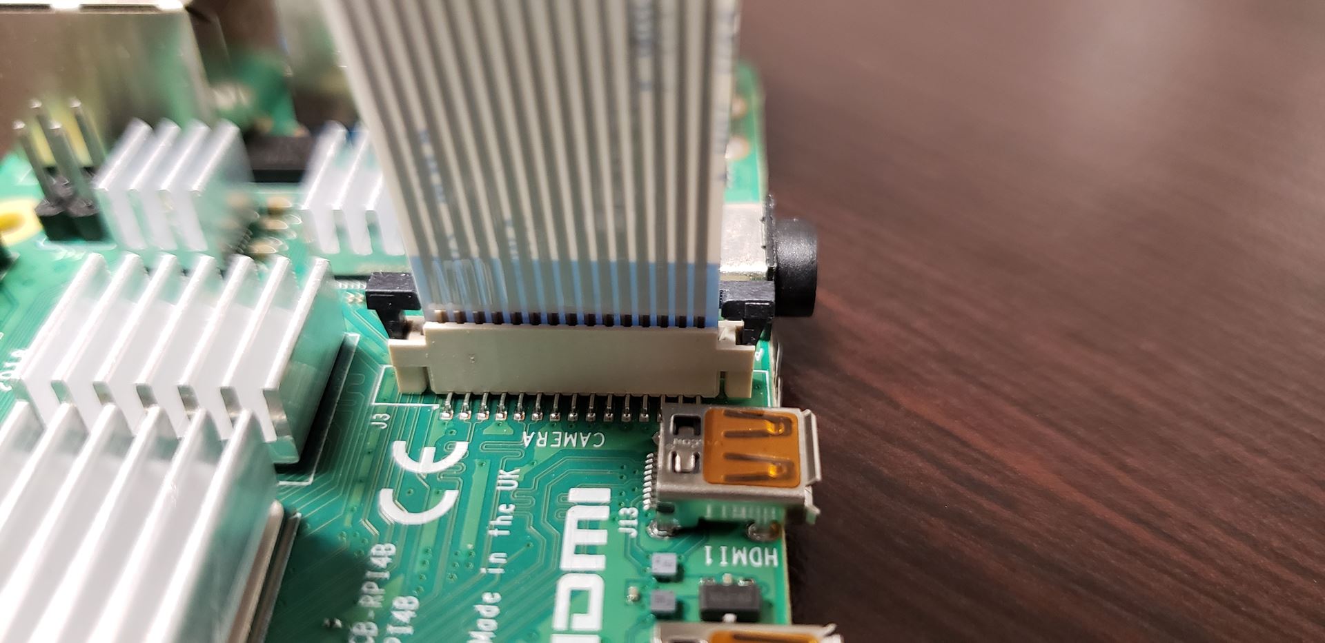
Warning
Pay attention to the orientation of the pins on the ribbon cable. If installed incorrectly, it will short the camera or the pi itself. In this case, the pins on the ribbon cable should be facing the micro HDMI ports.
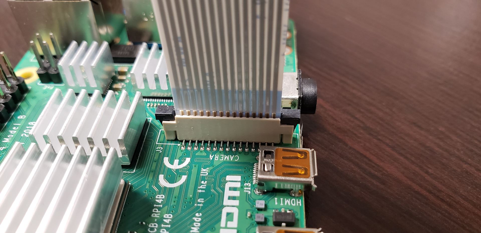
The CSI connector tab can now be pushed down to lock the ribbon cable in place. Give the ribbon cable a gentle tug to make sure it is secure.
Reassembling the VMX
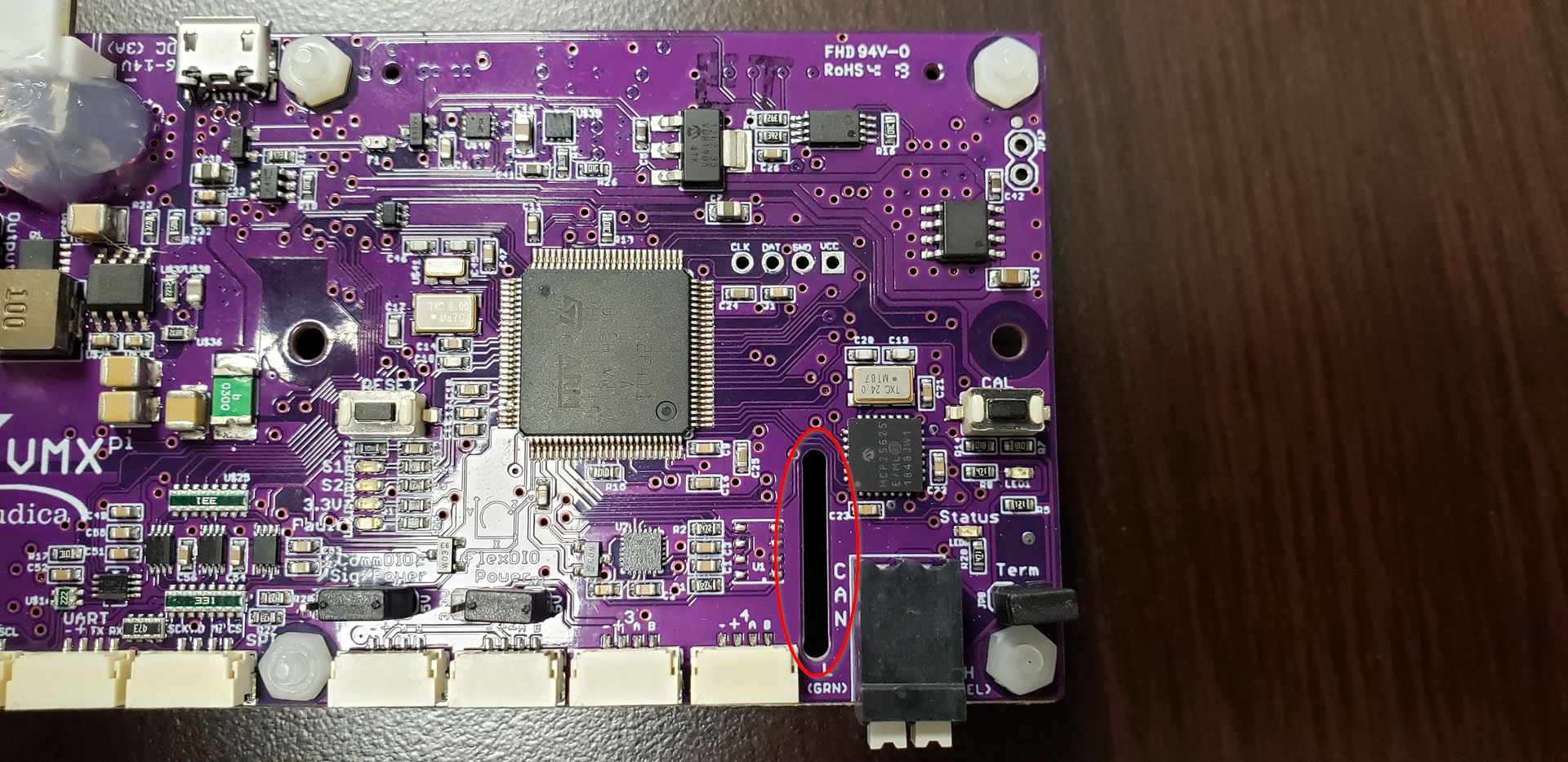
Notice the slot pictured above on the VMX-pi board. This is where the ribbon cable will slot through when the board is placed back onto the Raspberry Pi.
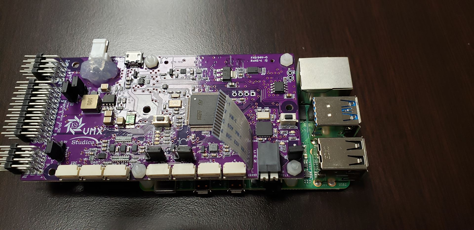
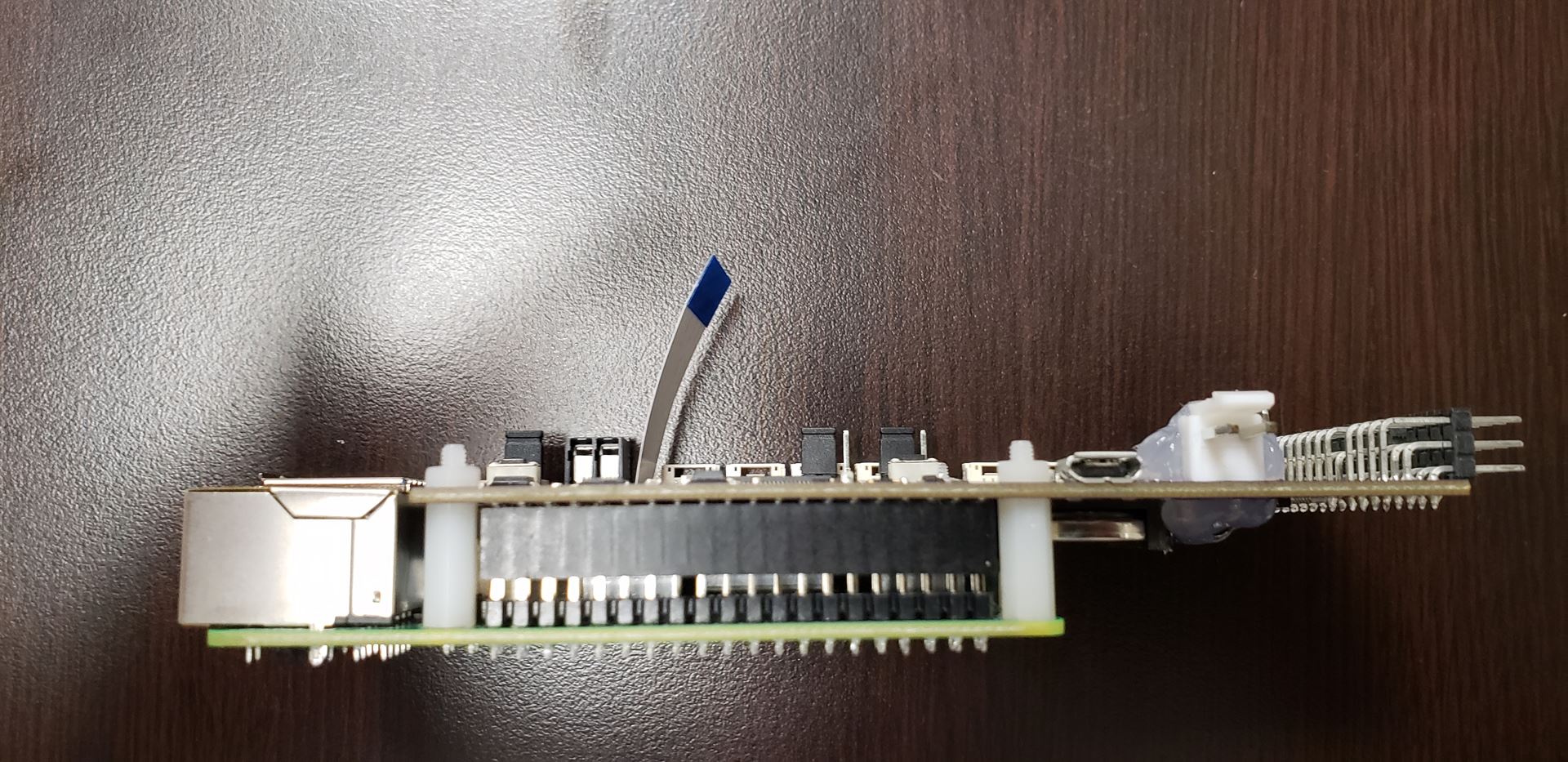
When the boards are placed back together, it should look like the above two pictures.
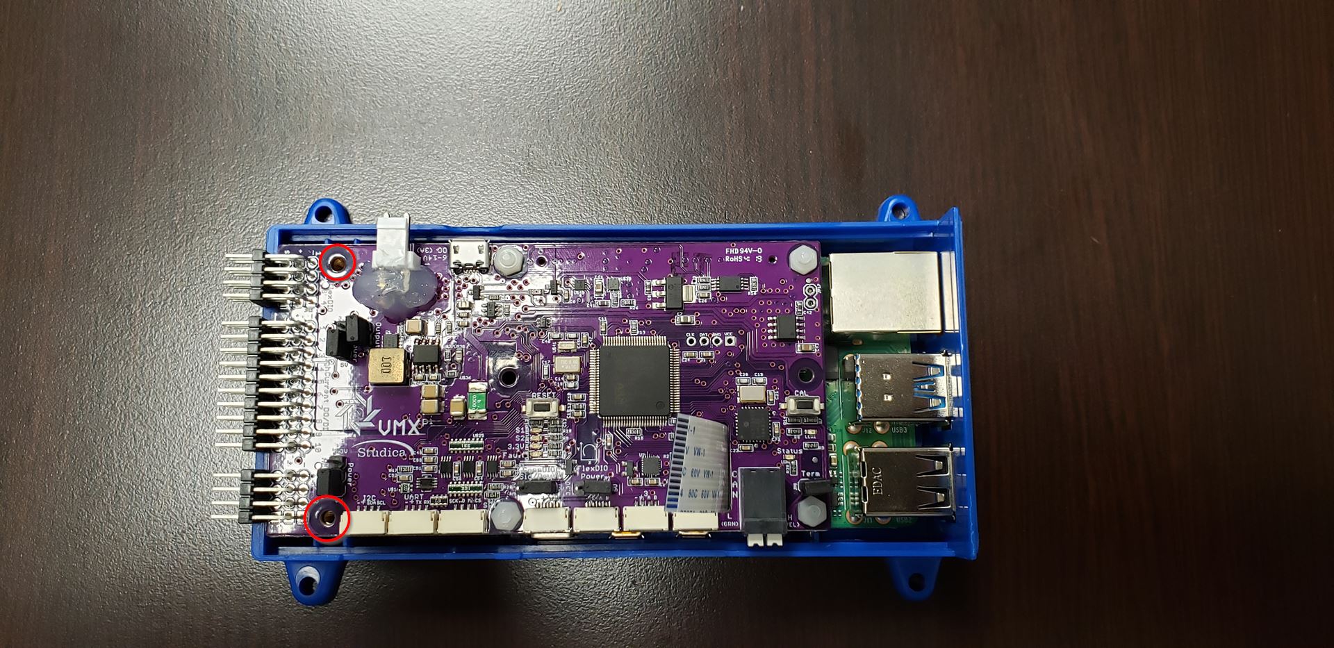
Place the VMX back into the bottom case and install the two screws highlighted above. Once the two screws are in place, turn the VMX on to its side and install the bottom 4 screws.
The lid can now be installed on the VMX. Note the highlighted area is where the ribbon cable will slot through.
To install the lid, turn it on its side, as shown above.
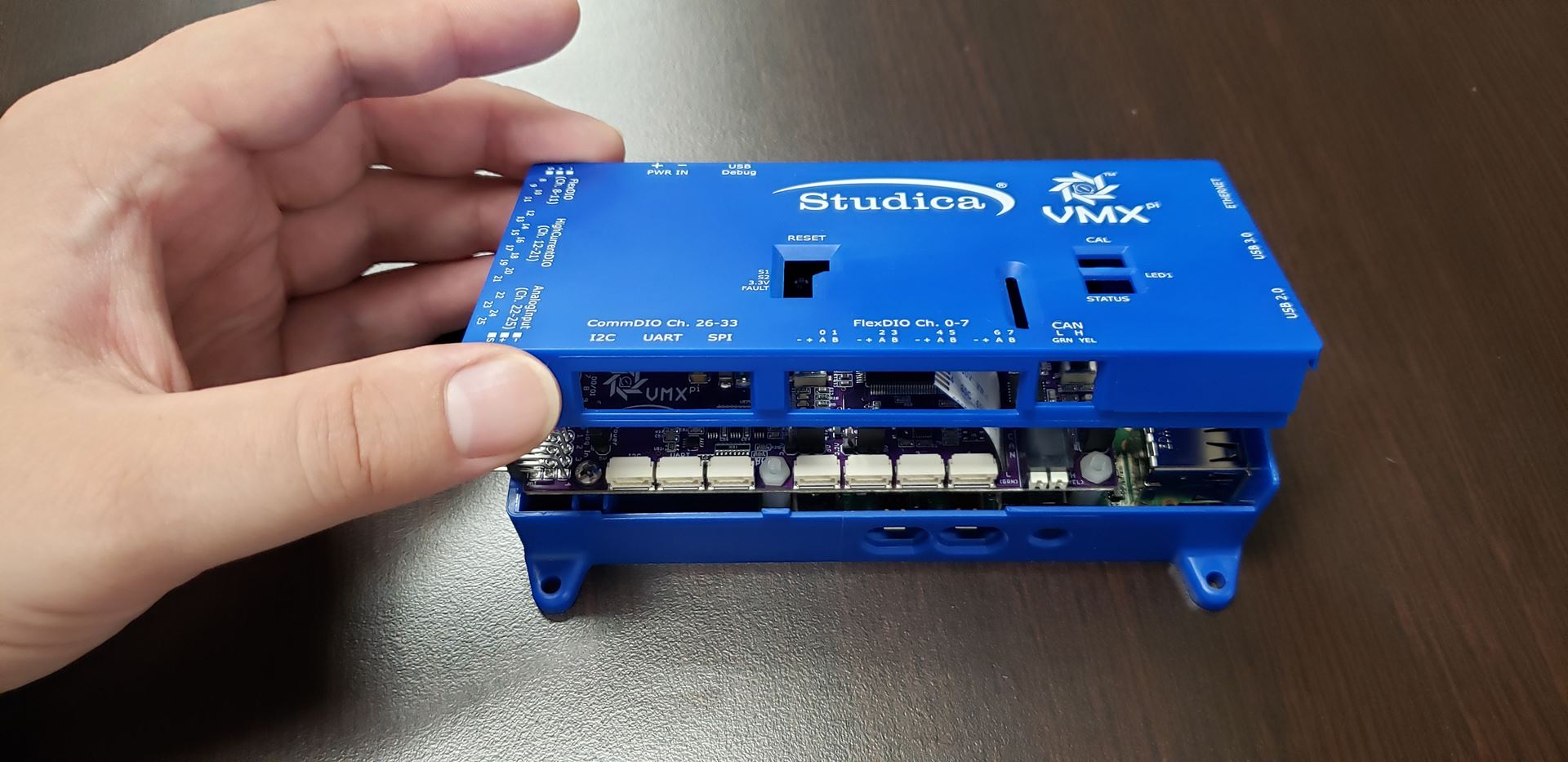
Turn the lid down to close. Note that the ribbon cable should slide through the slot on the lid before closing.
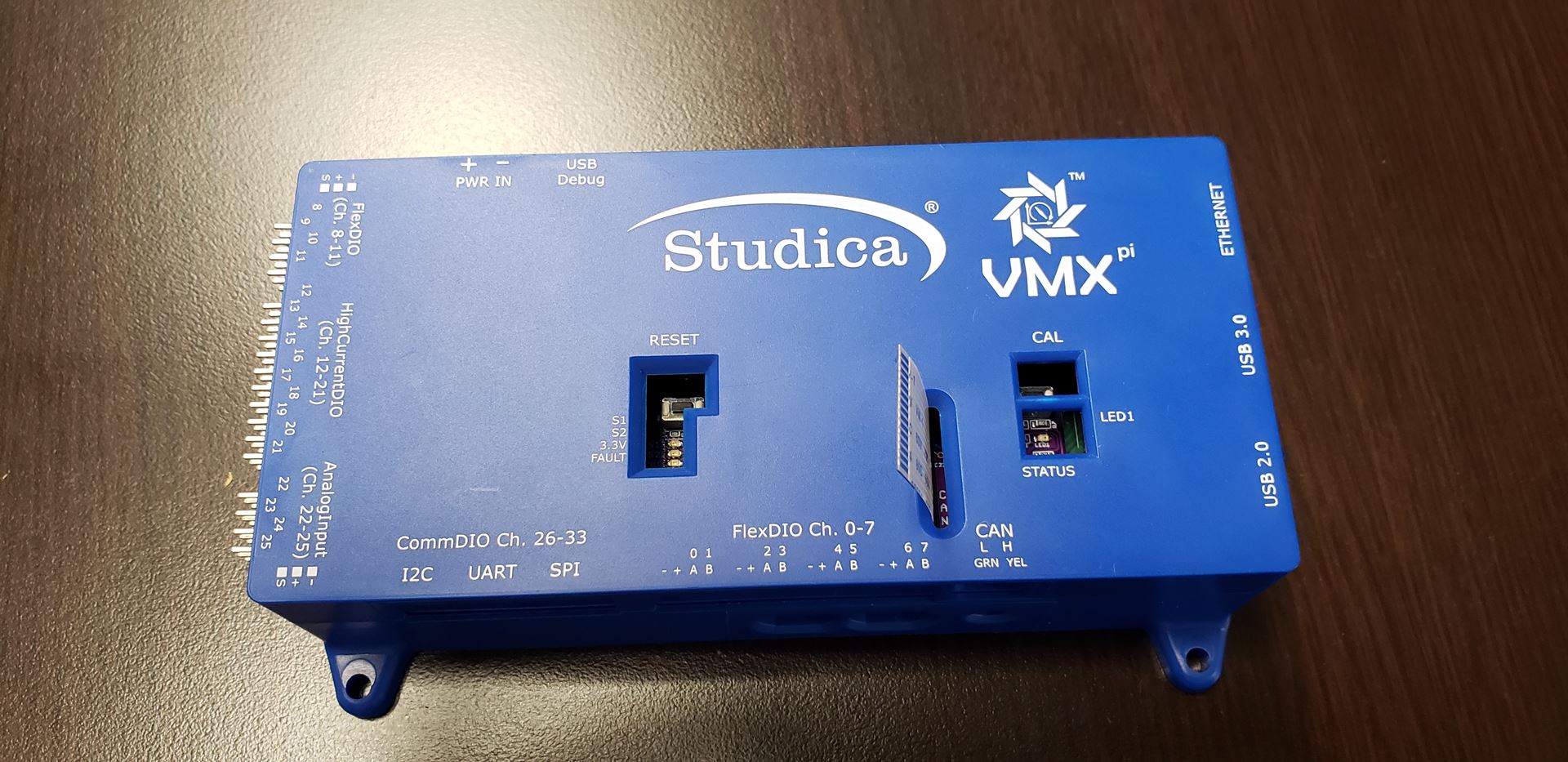
The VMX is now be assembled with the ribbon cable installed.
Adding the HDMI Adatper
Note
Pay attention location of the pins on the ribbon cable.
The HDMI Adapter Board is shown above in the correct orientation for the ribbon cable. The CSI connector tab should be open so that the ribbon cable can be inserted.

Once the ribbon cable is inserted, the tab can be closed. The installation of the ribbon cable into the VMX is now complete.