Connecting Sensors and Actuators
The VMX Robotics Controller provides a large number of electrical power and signal “pins” which connect to external devices including Sensors and Actuators.
Note
This summary of VMX IO configuration is sufficient for most robot Programming uses; more detailed information is available in the Hardware Reference Manual.
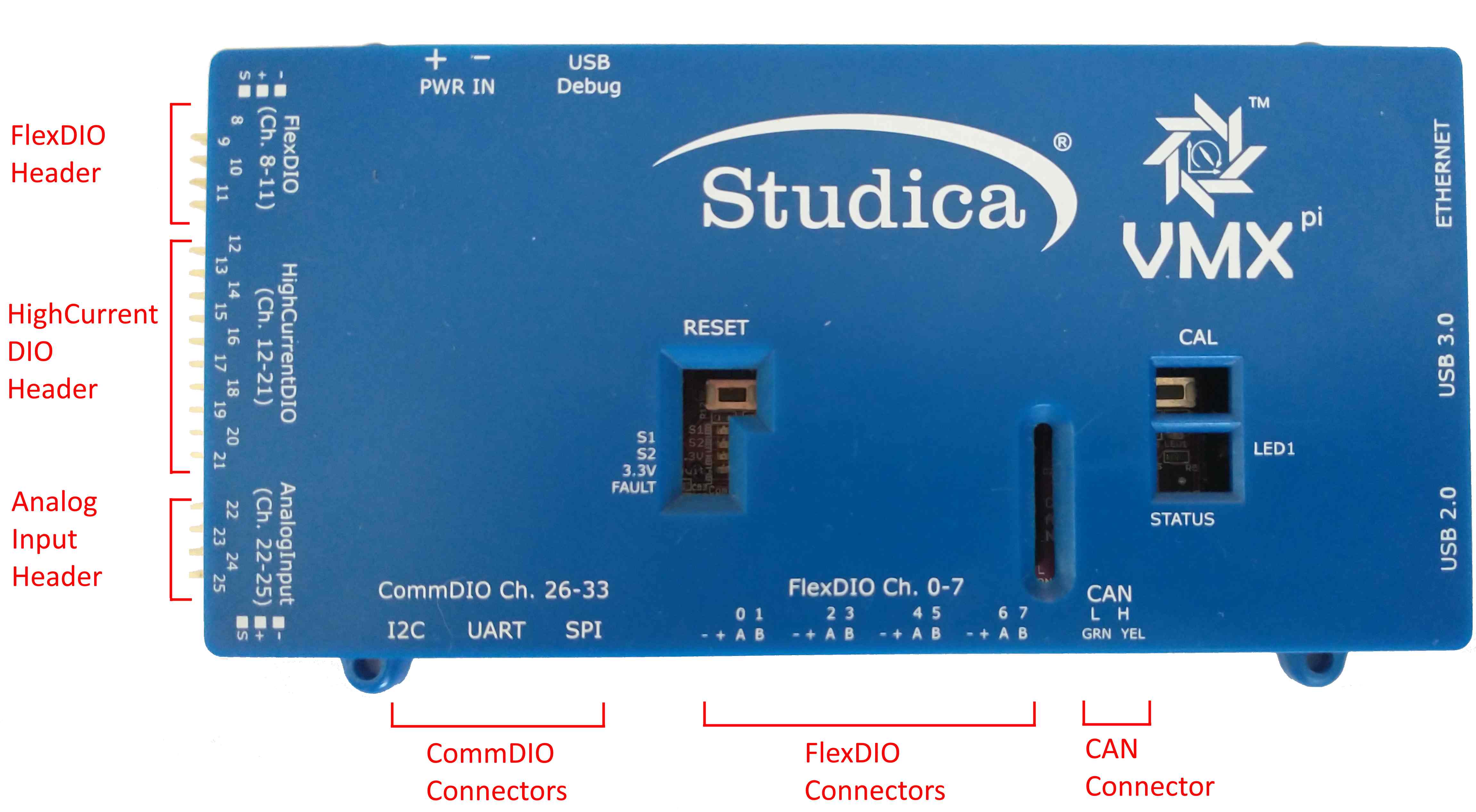
VMX Connector Blocks
VMX provides several different Connector Blocks.
Connector Block |
Connector Type |
Location on VMX |
|---|---|---|
Flex DIO Header |
3-pin PWM-style |
Left-side Top |
High Current DIO Header |
3-pin PWM-style |
Left-side mid |
Analog Input Header |
3-pin PWM-style |
Left-side bottom |
Comm DIO Connectors |
4-pin JST GH |
Bottom-left |
Flex DIO Connectors |
4-pin JST GH |
Bottom-middle |
CAN Connector |
2-wire Weidmuller |
Bottom-right |
Three (3) types of Connectors are used:
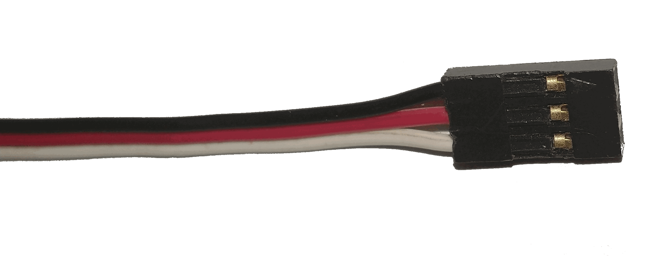
3-pin PWM-style Connector
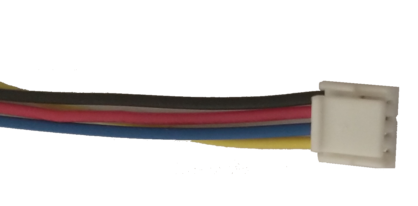
4-pin JST GH Connector
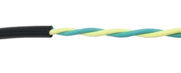
2-Wire CAN Wire
3-pin PWM-style Connectors, JST GH Connectors and Breakout Boards and CAN Wires are available for purchase online.
FlexDIO Connectors
FlexDIO Connectors are a set of four locking JST GH connectors (4 pins each) with power, ground, signal A and signal B on each connector. These connectors are designed to support Quadrature Encoders, but may also be configured for use as Digital Inputs, Interrupts, Digital Outputs, PWM Generators or Counters.
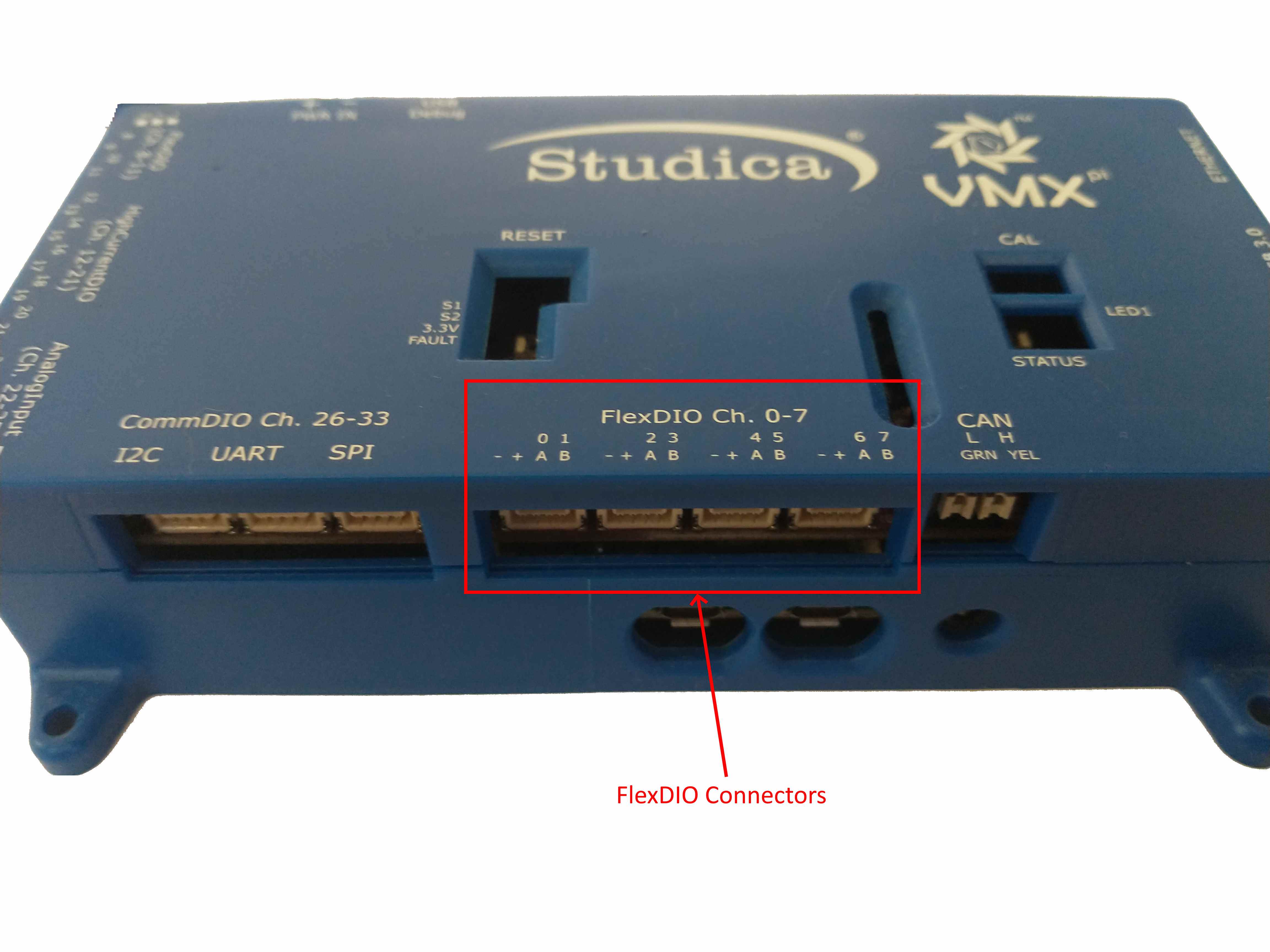
FlexDIO Connectors
FlexDIO Header
The FlexDIO Header provides 4 sets of power, ground, and a single signal channel. The signals may be configured to support Quadrature Encoders, Digital Inputs, Interrupts, Digital Outputs, PWM Generators or Counters. Note that only 2 of the pins on this header support Quadrature Encoders, see below for details.
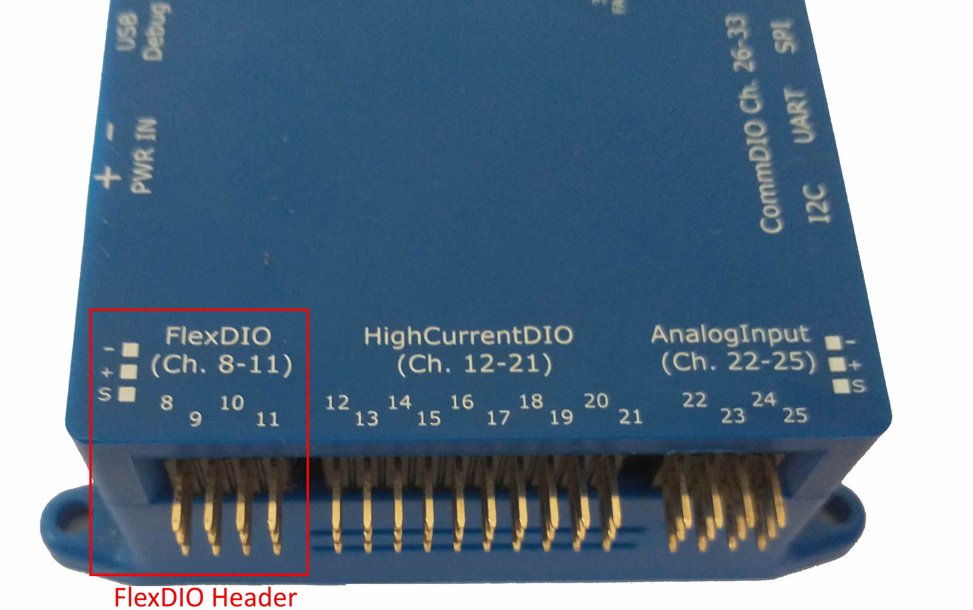
FlexDIO Header
CAN Connector
The CAN Connector accepts a pair of wires (CANH and CANL signals) with bare ends, which connect to a CAN bus.
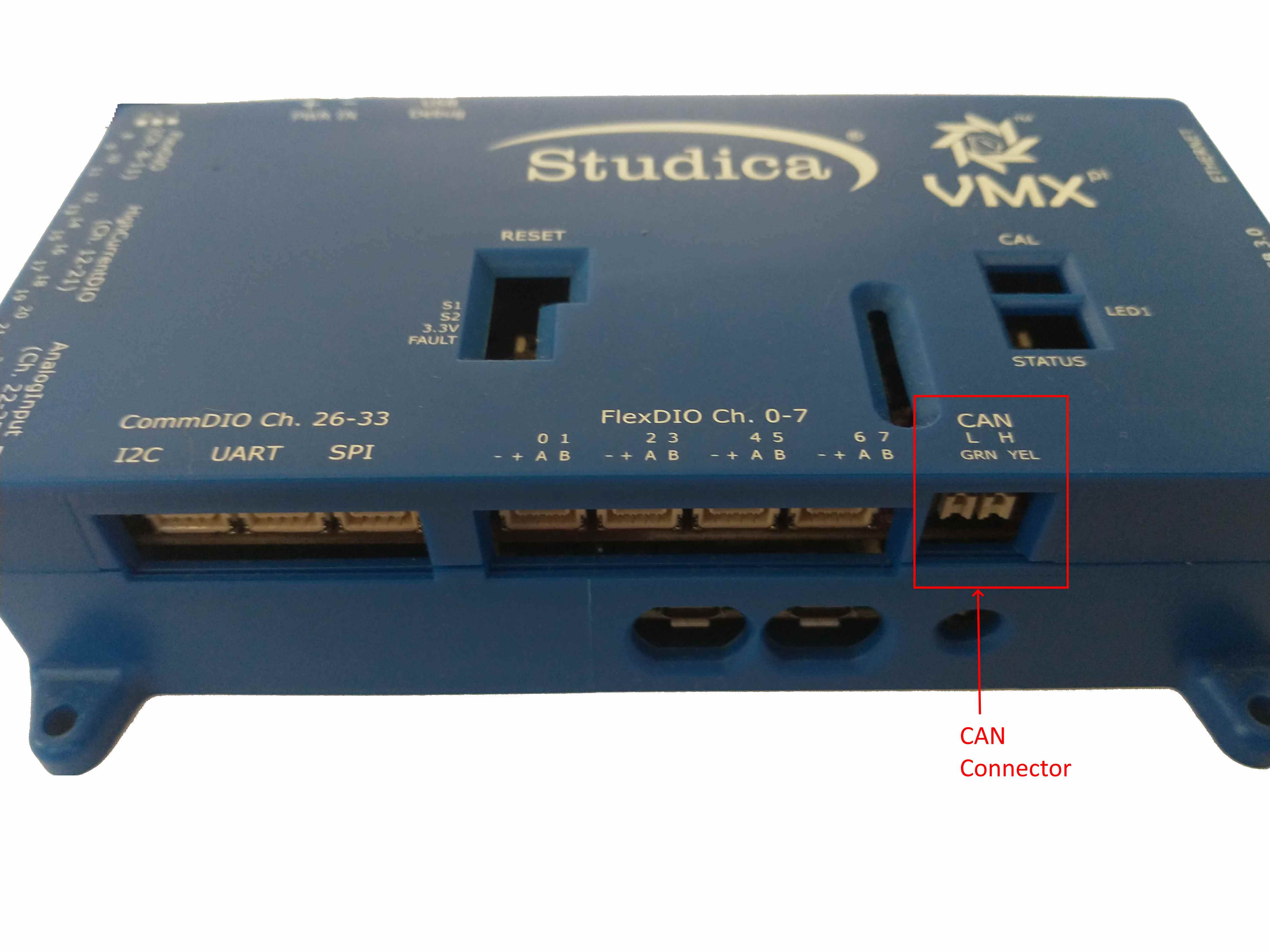
CAN Connector
High-Current DIO Header
The High-Current DIO Header provides 10 sets of power, ground, and a single signal channel. The signals may be configured to support Digital Inputs, Interrupts, Digital Outputs, PWM Generators or Relays.
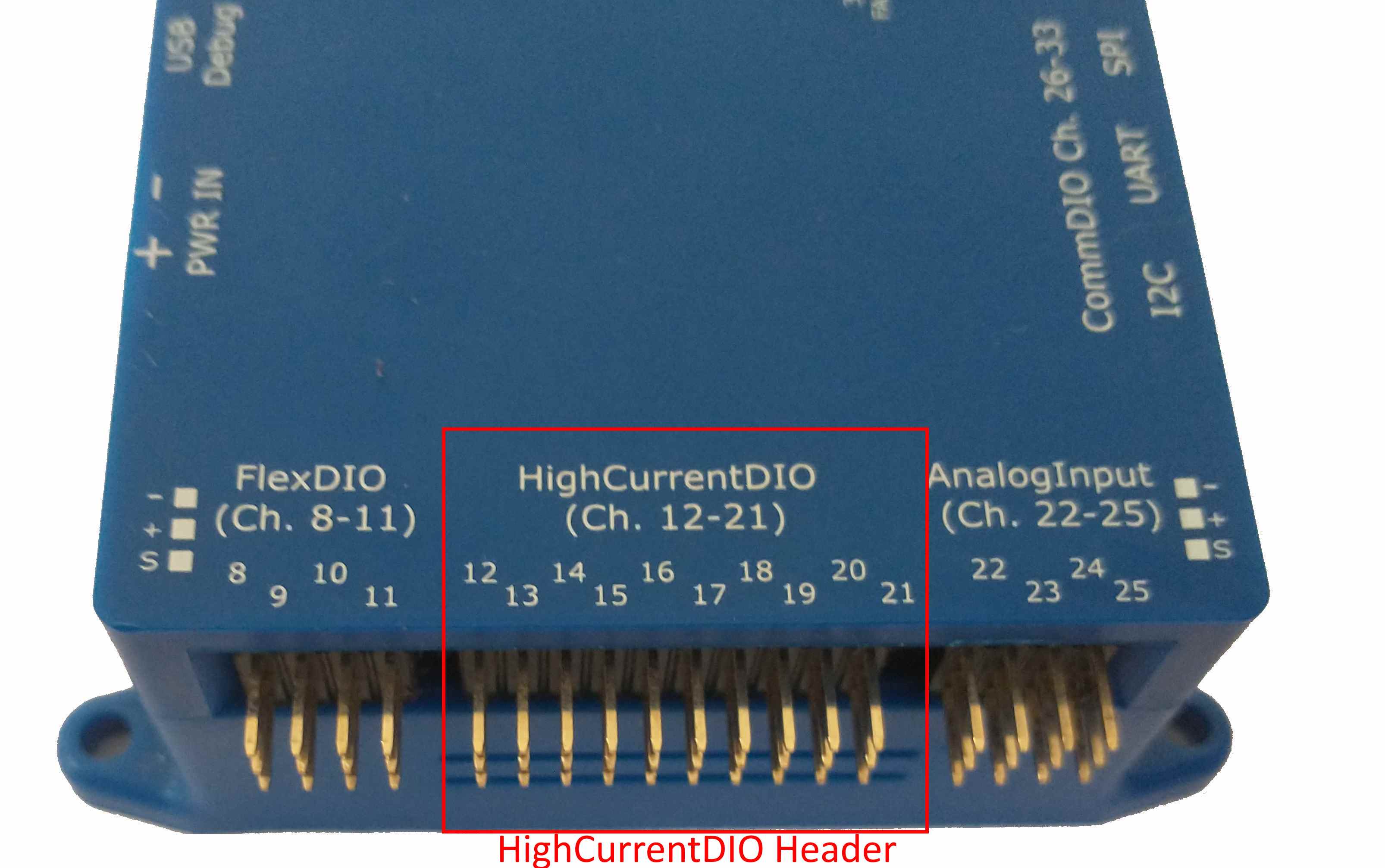
High-Current DIO Header
Note
The High-Current DIO Header may be configured in either Output or Input Direction, see below for details.
Analog Input Header
The Analog Input Header provides 4 sets of power, ground, and a single signal channel. The signals may be configured to support Analog Accumulation and/or Analog-triggered Interrupts.
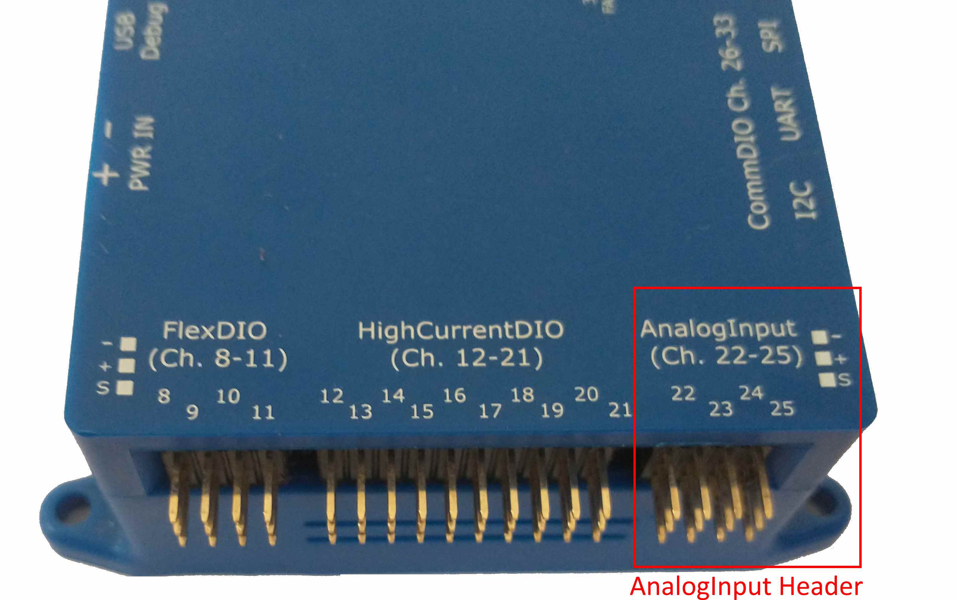
Analog Input Header
CommDIO Connectors
The three (3) CommDIO Connectors are three locking JST GH connectors (4 pins each) with different sets of power/ground/signals. Each connector may be configured to communicate using the corresponding digital communication protocol. Alternatively, the Input Channels may be configured for use as Digital Inputs or Interrupts; Output Channels may be configured for use as Digital Outputs or PWM.
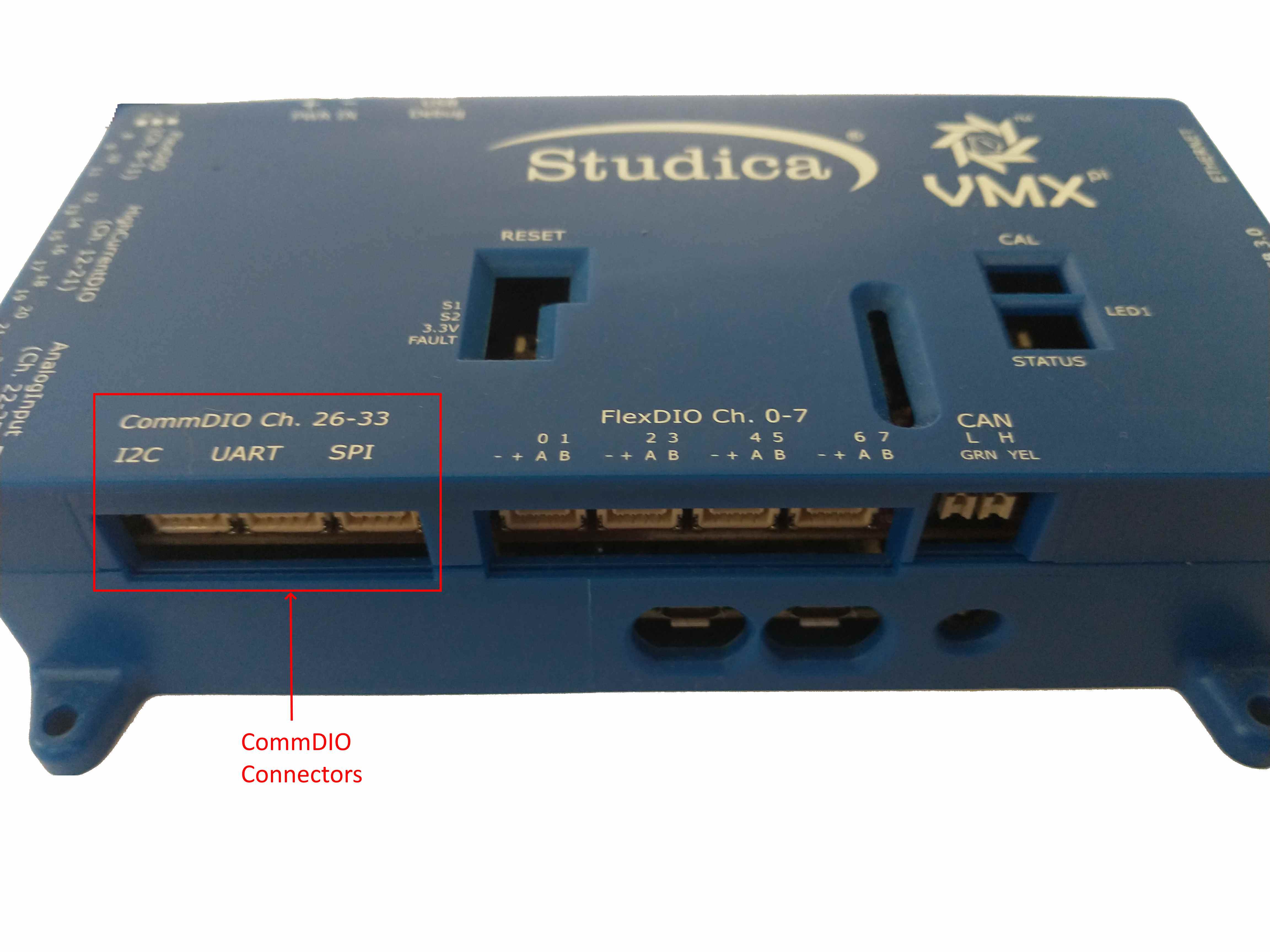
CommDIO Connectors
Each of the four pins on each connector have a different definition, depending upon the type:
I/O Channel Type Pin 1 |
Pin 2 |
Pin 3 |
Pin 4 |
|
|---|---|---|---|---|
I2C |
Ground |
Power (5 or 3.3V) |
SDA [OUTPUT] |
SCL [OUTPUT] |
TTL UART |
Ground |
Power (5 or 3.3V) |
TX [OUTPUT] |
RX [INPUT] |
SPI |
SCK [OUTPUT] |
MOSI [OUTPUT] |
MISO [INPUT] |
CS [OUTPUT] |
Note
Unlike the I2C and TTL UART Connectors, the SPI connector has 4 signal pins and does not provide power and ground.
Output Voltage Selection
Either 5 or 3.3V power output for external devices (both power and signal level) may be selected for Flex, High Current and Comm DIOs and also for power pins on the Analog Input Header.
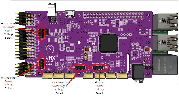
Output Voltage Selection Jumpers
Caution
If any of the external devices connected to pins in any of these groups are not 5V tolerant, ensure the voltage selection jumper is set to 3.3V to avoid damage to the external device.
Note
The Output Voltage Selection Jumper can only be accessed by opening the VMX enclosure.
High Current DIO Channel Direction configuration
The entire bank of High Current DIOs can be either all outputs (default), or all inputs. Direction selection is performed in hardware via the High Current DIO Input/Output Jumper. If the jumper is present, all High Current DIOs function as outputs, otherwise they function as inputs.
Output Configuration: 10 High Current DIO Pins are Digital Outputs Input Configuration: 10 High Current DIO Pins are Digital Inputs
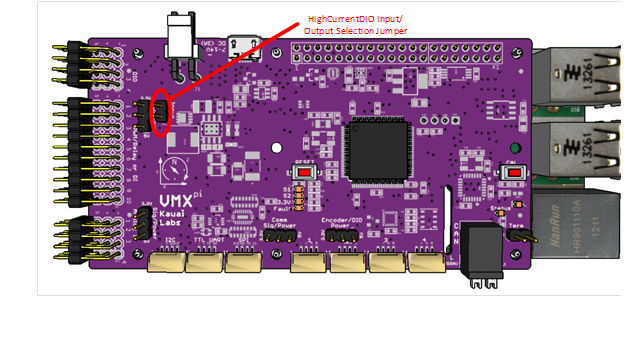
High Current DIO Channel Direction Jumper
The High Current Direction setting impacts the behavior of PWM, Relay and Digital IO Channels, described further below. Therefore this setting is one of the first things to verify in case of improper operation of the High Current DIO Channels.
Tip
Use the default Direction (Output) unless your configuration requires more digital inputs.
Note
The Output Voltage Selection Jumper can only be accessed by opening the VMX enclosure.