Encoders
Encoders are a sensor placed normally on a shaft to provide feedback to controller. This feedback allows for the detection of position, speed and direction of motion control system. There are two types of encoders; absolute and incremental. Absolute encoders report back a location specfic position. Incremental encoders only indicate that there has been a change in postion and what that change was. In robotics we tend to mostly use incremental encoders as they are easier to use and have some more benefical advandages than that of the absolute encoder.
The encoders in the worldskills collection are built into the motors already. This makes it easier for designing drive systems as an external encoder does not need to be designed in.
Distance Formula
Math
There is a lot of math assosiated with encoders. Before the encoder class can be used the distance per tick has to be calculated. The formula can be given as:
Where:
r= wheel radiusticksPerRev= encoder pulses on the output shaft of the motorgearRatio= an external gear ratio used.
Example
Lets look at an example using the Maverick with the 100mm omni wheel attached directly on the shaft of the motor.
r= 51 mm (actual measured value)ticksPerRev= 1464 (encoder counts per 1 revolution of the motor output shaft)gearRatio= 1:1
Therefor we can conculde that the distancePerTick for the Maverick using the 100mm omni wheels is 0.218881455.
Application
Now that we have the distancePerTick we can calculate the distance traveled. This is simply formulated by:
Where:
distancePerTick= 0.218881455encoderCount= is the incremental count from the encoder
Lets look at a few examples:
One Wheel Rotation
encoderCount = 1464
Note
The distance measured is in mm as the radius was specficed in mm.
Ten Wheel Rotations
encoderCount = 14640
Code
Now that we know the math behind it, let’s look at how to program the encoder for distance measurement.
Constants.java
1 2 3 4 5 6 7 8 9 10 11 12 13 14 15 16 17 18 19 20 21 22 23 24 | /** * Motor Constants */ public static final int TITAN_ID = 42; public static final int MOTOR = 2; /** * Encoder Constants */ //Radius of drive wheel in mm public static final int wheelRadius = 51; //Encoder pulses per rotation of motor shaft public static final int pulsePerRotation = 1464; //Gear ratio between motor shaft and output shaft public static final double gearRatio = 1/1; //Pulse per rotation combined with gear ratio public static final double encoderPulseRatio = pulsePerRotation * gearRatio; //Distance per tick public static final double distancePerTick = (Math.PI * 2 * wheelRadius) / encoderPulseRatio; |
Subsystem
1 2 3 4 5 6 7 8 9 10 11 12 13 14 15 16 17 18 19 20 21 22 23 24 25 26 27 28 29 30 31 32 33 34 | import com.studica.frc.TitanQuad; import com.studica.frc.TitanQuadEncoder; public class Subsystem { /** * Motors */ private TitanQuad motor; /** * Sensors */ private TitanQuadEncoder encoder; public Subsystem() { //Motors motor = new TitanQuad(Constants.TITAN_ID, Constants.MOTOR); //Sensors encoder = new TitanQuadEncoder(motor, Constants.MOTOR, Constants.distancePerTick); } /** * Gets the distance traveled of the motor * <p> * @return the distance traveled */ public double getEncoderDistance() { return encoder.getEncoderDistance(); } } |
1 2 3 4 5 6 7 8 9 10 11 12 13 14 15 16 17 18 19 20 21 22 23 24 25 26 27 28 29 30 31 32 33 34 35 36 37 38 39 40 41 42 43 44 | #include <studica/TitanQuad.h> #include <studica/TitanQuadEncoder.h> #include <cmath> class Subsystem : public frc2::SubsystemBase { public: Subsystem(); double GetEncoderDistance (void); private: /** * Motor Constants */ #define TITAN_ID 42 #define MOTOR_N 2 /** * Encoder Constants */ //Radius of drive wheel in mm #define wheelRadius 51 //Encoder pulses per rotation of motor shaft #define pulsePerRotation 1464 //Gear ratio between motor shaft and output shaft #define gearRatio 1/1 //Pulse per rotation combined with gear ratio #define encoderPulseRatio pulsePerRotation * gearRatio //Distance per tick #define distancePerTick (M_PI * 2 * wheelRadius) / encoderPulseRatio /** * Objects */ studica::TitanQuad motor{TITAN_ID, MOTOR_N}; studica::TitanQuadEncoder encoder{motor, MOTOR_N, distancePerTick}; }; |
1 2 3 4 5 6 7 8 9 10 11 12 13 | #include "subsystems/Subsystem.h" Subsystem::Subsystem(){}; /** * Gets the distance traveled of the motor * <p> * @return the distance traveled */ double Subsystem::GetEncoderDistance (void) { return encoder.GetEncoderDistance(); } |
Speed
Besides distance, the encoder can also provide the speed of the motor. Speed can be represented in two main ways rpm and m/s. Both have advantages and disadvantages but are also easy to implement.
Rotations Per Minuite (RPM)
The RPM is the number of revolutions of the motor shaft every minute. For example, the Maverick DC Motor has a nominal RPM of 100. However, all motors will rarely rotate at the same speed. With the encoder, some math and the RPM can be calculated to use in formulas if required.
Important
The RPM does not consider any gear ratios or the size of the output object, i.e., wheel.
Fortunately, the Titan has an internal RPM count, so no external math is required. It is as simple as calling the getRPM() functions.
Constants.java
1 2 3 4 5 | /** * Motor Constants */ public static final int TITAN_ID = 42; public static final int MOTOR = 2; |
Subsystem
1 2 3 4 5 6 7 8 9 10 11 12 13 14 15 16 17 18 19 20 21 22 23 24 25 | import com.studica.frc.TitanQuad; public class Subsystem { /** * Motors */ private TitanQuad motor; public Subsystem() { //Motors motor = new TitanQuad(Constants.TITAN_ID, Constants.MOTOR); } /** * Gets the RPM of the motor * <p> * @return the RPM of the motor */ public double getRPM() { return motor.getRPM(Constants.MOTOR); } } |
1 2 3 4 5 6 7 8 9 10 11 12 13 14 15 16 17 18 19 20 21 | #include <studica/TitanQuad.h> class Subsystem : public frc2::SubsystemBase { public: Subsystem(); double GetRPM (void); private: /** * Motor Constants */ #define TITAN_ID 42 #define MOTOR_N 2 /** * Objects */ studica::TitanQuad motor{TITAN_ID, MOTOR_N}; }; |
1 2 3 4 5 6 7 8 9 10 11 12 13 | #include "subsystems/Subsystem.h" Subsystem::Subsystem(){}; /** * Gets the RPM of the motor * <p> * @return the RPM of the motor */ double Subsystem::GetRPM (void) { return encoder.GetRPM(MOTOR_N); } |
Tip Speed or Velocity
RPM is excellent to have, but it does not give the actual speed of the object, such as a wheel. RPM only gives the speed of the motor shaft. In comes a simple formula to convert RPM to Tip Speed or Velocity.
Math
Where
D= Diameter of wheel in metersπ= piS= rpm60= conversion from minutes to seconds
Example
Diameterof the wheel is0.102m.πis π.Sis the nominal speed of the Maverick at100rpm.
Application
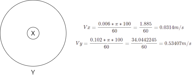
When looking at the diagram above, the speed is only 0.0314m/s if using just RPM. When calculating for Y the proper speed is given at 0.53407m/s. There is a clear difference between the two speeds. This can conclude that while the RPM is excellent, it is better to incorporate the adjusted Tip Speed or Velocity in equations to give more accuracy.