Calibrating and Using the navX-sensor IMU
VMX includes an internal navX-Sensor IMU, comprised of 3 gyroscopes, 3 accelerometers, 3 magnetometers and a motion processor which processes data from these sensors and generates measurements of angular orientation and linear acceleration.
Basic Usage
Orientation
VMX measures a total of 9 sensor axes (3 gyroscope axes, 3 accelerometer axes and 3 magnetometer axes) and fuses them into a 3-D coordinate system. In order to effectively use the values reported by VMX, a few key concepts must be understood in order to correctly install VMX on a robot.
3-D Coordinate System
When controlling a robot in 3 dimensions a set of 3 axes are combined into a 3-D coordinate system, as depicted below:
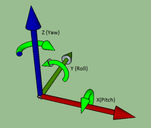
navX-Sensor Coordinate System
In the diagram above, the green rounded arrows represent Rotational motion, and the remaining arrows represent Linear motion.
Axis |
Orientation |
Linear Motion |
Rotational Motion |
|---|---|---|---|
X (Pitch) |
Left/Right |
|
|
Y (Roll) |
Forward/Backward |
|
|
Z (Yaw) |
Up/Down |
|
|
Reference Frames
Note that the 3-axis coordinate system describes relative motion and orientation; it doesn’t specify the orientation with respect to any other reference. For instance, what does “left” mean once a robot has rotated 180 degrees?
To address this, the concept of a reference frame was invented. There are three separate three-axis “reference frames” that should be understood:
Coordinate System |
Reference Frame |
X Axis |
Y Axis |
|---|---|---|---|
Field |
World Frame |
Side of Field |
Front (Head) of Field |
Robot |
Body Frame |
Side of Robot |
Front (Head) of Robot |
navX-sensor |
Board Frame |
See diagram Below |
See diagram below |
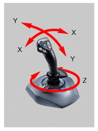
Joystick Axes Orientation
Since a three-axis joystick is typically used to control a robot, the robot designer must select upon which Reference Frame the driver joystick is based. This selection of Reference Frame typically depends upon the drive mode used:
Drive mode |
Reference Frame |
Coordinate Orientation |
|---|---|---|
Standard Drive |
Body Frame |
Forward always points to the front (head) of the robot |
Field-oriented Drive |
World Frame |
Forward always points to the front (head) of the field |
VMX Board Orientation
Aligning Board Frame and Body Frame
In order for the VMX orientation sensor readings to be easily usable by a robot control application, the VMX Coordinate System (Board Frame) must be aligned with the Robot Coordinate system (Body Frame).
Aligning the Yaw (Z) axis and Gravity
The VMX motion processor takes advantage of the fact that gravity can be measured with its onboard accelerometers, fusing this information with the onboard gyroscopes to yield a very accurate yaw reading with a low rate of drift. In order to accomplish this, the yaw (Z) axis must be aligned with the “gravity axis” (the axis that points directly up and down with respect to the earth).
When installing VMX on a robot, the VMX yaw (Z) axis and the gravity axis must be aligned.
Default VMX Board Orientation
The default VMX circuit board orientation is with the VMX logo on the Front Right, with the top of the circuit board pointing up (with respect to the earth).
Since Body Frame and Board Frame coordinates should be aligned, and because the Yaw axis must be aligned with gravity, by default you must orient the VMX with the top of the board facing up, and with the Y axis (on the circuit board) pointing to the front of the robot.
If you need to mount the VMX circuit board in a different orientation (vertically, horizontally, or upside down), you can use the OmniMount feature to transform the orientation.
Gyroscope/Accelerometer Calibration
VMX onboard orientation sensors require calibration in order to yield optimal results. We highly recommend taking the time to understand this calibration process – successful calibration is vital to ensure optimal performance.
Accurate Gyroscope Calibration is crucial in order to yield valid yaw angles. Although this process occurs automatically, understanding how it works is required to obtain the best results.
Important
If you are tempted to ignore this information, please read the section entitled “The Importance of Stillness” at the end of this section.
Calibration Process
The VMX Calibration Process is comprised of three calibration phases:
Factory Calibration
Startup Calibration
On-the-fly Calibration
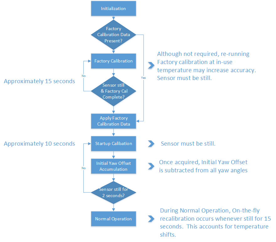
navX-Sensor Calibration Process
Factory Calibration
Before VMX units are shipped, the accelerometers and gyroscopes are initially calibrated at the factory; this calibration data is stored in flash memory and applied automatically to the accelerometer and gyroscope data each time the navX-Micro circuit board is powered on.
Note that the onboard gyroscopes are sensitive to temperature changes. Therefore, since the average ambient temperature at the factory (on the island of Kauai in Hawaii) may be different than in your environment, you can optionally choose to re-calibrate the gyroscope by pressing and holding the “CAL” button for at least 10 seconds. When you release the “CAL” button, ensure that the “CAL” Led flashes briefly, and then press the “RESET” button to restart navX-Micro. When VMX is re-started, it will perform the Initial Gyro Calibration – the same process that occurs at our factory. NOTE: It is very important to hold VMX still, and parallel to the earth’s surface, during this Initial Gyro Calibration period. You might consider performing this process before using your robot the first time it is used within a new environment (e.g., when you arrive at a FTC competition event).
The value of re-running Factory Calibration at the same temperature VMX will be operated at is potentially increased yaw accuracy as well as faster Startup Calibration. If a significant temperature shift has occurred since the last Factory Calibration, the Startup Calibration time may take longer than normal, and it’s possible that yaw accuracy will be diminished until the next On-the-fly Gyro Calibration completes.
Startup Calibration
Startup Calibration occurs each time VMX is powered on, and requires that the sensor be held still in order to complete successfully. Using the Factory Calibration as a starting point, the sensor calibrates the accelerometers and adjusts the gyroscope calibration data as well based upon current temperature conditions.
If the sensor continues to move during startup calibration, Startup Calibration will eventually timeout – and as a result, the VMX yaw angle may not be as accurate as expected.
Initial Yaw Offset Calibration
Immediately after Startup Calibration, an Initial Yaw Offset is automatically calculated. The purpose of the Initial Yaw Offset is to ensure that whatever direction the “front” of the VMX circuit board is pointed to at startup (after initial calibration is applied) will be considered “0 degrees”.
Yaw Offset Calibration requires that VMX be still for approximately 2 seconds after Startup Calibration completes. After approximately 2 seconds of no motion, VMX will acquire the current yaw angle, and will subtract it from future yaw measurements automatically. The VMX protocol and libraries provide a way to determine the yaw offset value it is currently using.
NOTE: If VMX is moving during startup, this Yaw Offset Calibration may take much longer than 2 seconds, and may not be calculated at all if the sensor continues moving long enough. Therefore it is highly-recommended to keep VMX still until initial calibration and Initial Yaw Offset calibration completes.
On-the-fly Gyro Calibration
In addition to Startup Calibration, during normal operation VMX will automatically re-calibrate the gyroscope (e.g., to account for ongoing temperature changes) during operation, whenever it detects 8 seconds of no motion. This process completes after about 7-8 more seconds, and is completely transparent to the user. Therefore each time VMX is still for approximately 15 seconds, the gyroscopes are re-calibrated “on-the-fly”. The purpose of On-the-fly Gyro re-calibration is to help maintain yaw accuracy when shifts in ambient temperature occur during operation.
This On-the-fly Gyro Calibration can help deal with cases where the sensor was moving during Startup Calibration, but note that the yaw is not zeroed at the completion of On-the-fly Calibration. So once again, it’s important to keep the sensor still during Startup Calibration.
Runtime Yaw Zeroing
Your robot software can optionally provide the robot operator a way to reset the yaw angle to Zero at any time. Please see the documentation for the VMX libraries for more details.
The importance of stillness
Important
This is the most important takeaway from this discussion: It is highly-recommended that VMX be held still during the above Initial Gyro and Initial Yaw Offset calibration periods. In support of this, VMX indicates when it is calibrating; we recommend you incorporate this information into your software. Please see the discussion of the navXUI, and the VMX libraries for more details on this indication.
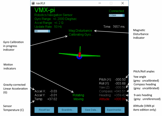
navXUI
The navXUI user interface application provides a simple way to visualize the data provided by VMX.
navXUI
To install and run navXUI:
Download the VMX Tools for Windows latest build.
Unpack the contents of the vmx-pi.zip file and run the setup.exe program
Connect a USB cable between the VMX circuit board and your Windows computer.
From the Windows Menus, click on Kauai Labs->navXUI
Gyro Calibration in Progress Indicator
The Gyro Calibration in Progress Indicator is displayed during initial gyroscope calibration, which occurs immediately after power is applied to VMX. If the gyroscope calibration does not complete, VMX yaw accuracy will be adversely impacted. For more information on Gyro Calibration, please see the Gyro/Accelerometer Calibration page.
Motion Indicators
VMX provides dynamic motion indicators: (a) the “Moving” indicator and (b) the “Rotating” indicator.
The Moving indicator is present whenever the current Gravity-corrected Linear Acceleration exceeds the “Motion Threshold”.
The Rotating indicator is present whenever the change in yaw value within the last second exceeds the “Rotating Threshold”. Note that VMX Gyroscope Calibration only occurs when VMX is not Rotating for a few seconds.
Gravity-corrected Linear Acceleration (G)
VMX automatically subtracts acceleration due to gravity from accelerometer data, and displays the resulting linear acceleration. These measures are in units of instantaneous G, and are in World Reference Frame.
Sensor Temperature
The Sensor Temperature indicates the die temperature of the MPU-9250 IC. Since shifts in gyro temperature can impact yaw accuracy, VMX will automatically perform Gyroscope calibration whenever VMX is still. See the Gyro/Accelerometer Calibration page for more details.
Magnetic Disturbance Indicator
Once the VMX Magnetometer has been calibrated (see the Magnetometer Calibration page), whenever the current magnetic field diverges from the calibrated value for the earth’s magnetic field, a magnetic disturbance is indicated.
Yaw Angle
The Yaw Angle is displayed in grey text if Gyro Calibration has not yet been completed. Once Gyro Calibration is complete, the Yaw Angle text color will change to white.
Pitch/Roll Angles
The Pitch/Roll Angles are always displayed in white text, since Accelerometer calibration occurs at the Kauai Labs factory.
Compass Angle
The Compass Angle displays the tilt-compensated compass heading calculated from VMX’s Magnetometer combined with the tip/tilt measure from the Accelerometers.
The Compass Angle is displayed in grey text if Magnetometer Calibration has not yet been completed. Once Magnetometer Calibration is complete, the Compass Angle text color will change to white.
9-axis (“Fused”) Heading
The 9-axis heading is displayed in grey text if Magnetometer Calibration has not yet been completed and/or if no undisturbed magnetic readings have occurred.
Yaw Drift
A gyroscope measures the amount of angular rotation about a single axis. Since the gyroscope measures changes in angular rotation, rather than an absolute angle, calculation of the actual current angle of that axis is estimated via numerical integration rather than an exact measurement.
Any Inertial Measurement Unit (IMU), including the VMX_pi IMU, that integrates a signal from a gyroscope will also accumulate error over time. Accumulated error is due to several factors, including:
Quantization noise (which occurs when an analog-to-digital converter (ADC) converts a continuous analog value to a discrete integral value)
Scale factor error (which occurs due to manufacturing errors causing a specified scale factor [e.g., 256 bits per unit G] to be incorrect)
Temperature instability (which occurs when a sensor is more or less sensitive to an input as temperature changes)
Bias error (which occurs because the value the sensor reports at ‘zero’ is not known well enough to ‘subtract’ that value out during signal processing)
Over time, these errors accumulate leading to greater and greater amounts of error.
With the VMX orientation sensor, Quantization error is minimized due to the sensor internal signal conditioning, high-resolution 16-bit Analog-to-Digital Converters (ADC), and extremely fast internal sampling (200Hz). Scale factor error is easily corrected for by factory calibration, which VMX provides. So these two noise sources are not significant in VMX.
The remaining sources of error – temperature instability and bias error – are more challenging to overcome:
Gyro bias error is a major contributor to yaw drift error, but is inherent in modern MEMS-based gyroscopes used in the navX-Sensor.
Temperature instability can cause major amounts of error, and should be managed to get the best result. To address this, the navX-sensor automatically re-calibrates the gyro biases whenever it is still for several seconds, which helps manages temperature instability. Errors in the VMX Pitch and Roll values to be extremely accurate over time since gyroscope values in the pitch/roll axes can be compared to the corresponding values from the accelerometer. This is because when VMX is still, the accelerometer data reflects only the linear acceleration due to gravity.
Correcting for integration error in the Yaw axis is more complicated, since the accelerometer values in this axis are the same no matter how much yaw rotation exists.
To deal with this, several different “data fusion” algorithms have been developed, including the Extended Kalman Filter (EKF) used by the navX-sensor. THe EKF filter is designed to process 3-axis accelerometer and 3-axis gyroscope values and yield yaw/pitch/roll values.
With this processing, VMX exhibits yaw drift on the order of ~1 degree per minute; yaw drift is typically much lower when VMX is still.
Best Practices
This page summarizes the recommended best practices when integrating VMX with a robot. Following these best practices will help ensure high reliability and consistent operation.
Secure VMX circuit board to the Robot Chassis
Excessive vibration will reduce the quality of VMX orientation sensor measurements. The VMX circuit board should be mounted in such a way that it as firmly attached to the robot chassis.
Understand and Plan for Calibration
Gyro/Accelerometer Calibration is vital to achieving high-quality VMX IMU readings. Be sure to understand this process, and ensure that it completes successfully each time you use the robot.
If your robot moves during calibration, or if noticeable temperature changes occur during calibration, the calibration process may take longer than normal.
Using the VMX yaw angle before calibration completes may result in errors in robot control. To avoid this situation, your robot software should verify that calibration has completed before using VMX IMU data.
Protect the Circuitry
VMX contains sensitive circuitry. The VMX circuit board should be handled carefully.
An enclosure is recommended to protect the VMX circuit board from excessive handling, “swarf”, electro-static discharge (ESD) and other elements that could potentially damage VMX circuitry.
Provide a “Zero Yaw” feature (for Field-Oriented Drive)
The VMX gyro “yaw” angle will drift over time (approximately 1 degree/minute). While this does not normally impact the robot during a typical FRC match, if using field-oriented drive during extended practice sessions it may be necessary to periodically “zero” the yaw. Drivers should be provided a simple way (e.g., a joystick button) with which to zero the yaw.
If possible, mount VMX near the center of rotation
Since VMX measures rotation, errors in the measured angles can occur if VMX is mounted at a point not near the robot center of rotation. For optimal results, VMX should be mounted at the robot’s center of rotation. If VMX cannot be mounted near the robot’s center of rotation, the offset from the center of rotation can be used to correct the yaw angle.
Use OmniMount if VMX is not mounted horizontally
By default, VMX’s motion processing requires the unit be mounted horizontally, parallel to the earth’s surface; the yaw (Z) axis should be perpendicular to the earths surface.
If you need to mount VMX vertically or upside-down, you will need to enable the “OmniMount” feature in order to get reliable, accurate yaw (Z) axis readings.
Learn how the sensor behaves by using the navXUI
The navXUI provides insight into the key VMX IMU features, and can help debug issues you may encounter when integrating VMX onto your robot. Running this user interface is highly recommended for anyone using VMX.
Advanced Usage
Omnimount
If the VMX default yaw axis orientation isn’t sufficient for your needs, you can use the OmniMount feature to re-configure the VMX yaw axis, allowing high-accuracy yaw axis readings when VMX is mounted horizontally, vertically, or even upside down.
In certain cases, the VMX axes (Board Frame) may not be oriented exactly as that of the Robot (Body Frame). For instance, if the VMX circuit board is mounted sideways, the navX-Sensor axes will not be oriented identically to the Robot.
Transforming VMX Board Frame to Body Frame with OmniMount
VMX’s “OmniMount” feature can transform the VMX X, Y and Z axis sensor data (Board Frame) into Robot Orientation (Body Frame) by detecting which of its three axes is perpendicular to the earth’s surface.
This is similar to how a modern smart phone will rotate the display based upon the phone’s orientation. However unlike a smart phone, the OmniMount detection of orientation does not happen all the time – since the orientation should not change while the robot is moving. Rather, each time OmniMount configuration occurs, VMX records this transformation in persistent flash memory, and will continue to perform this transformation until the transform is reconfigured.
To configure OmniMount, follow these simple steps:
Install VMX onto your robot. ENSURE that one of the VMX axes (as shown on the VMX circuit board) is perpendicular to the earth’s surface. This axis will become the yaw (Z) axis. Note that this axis can either be pointing away from the earth’s surface, or towards the earth’s surface.
Press the ‘CAL’ button on the VMX Circuit board AND HOLD THE BUTTON DOWN FOR AT LEAST 5 SECONDS.
Release the ‘CAL’ button, and verify that the orange ‘CAL’ light flashes for 1 second and then turns off.
Press the ‘RESET’ button on the VMX circuit board, causing it to restart.
The VMX circuit board will now begin OmniMount auto-calibration. During this auto-calibration period, the orange ‘CAL’ LED will flash repeatedly. This process takes approximately 15 seconds, and requires two things: 1. During auto-calibration, one of the VMX axes MUST be perpendicular to the earth’s surface. 2. During auto-calibration, the VMX must be held still. If either of the above conditions is not true, the ‘CAL’ LED will be flashing quickly, indicating an error. To resolve this error, you must ensure that conditions 1 and 2 are met, at which point the ‘CAL’ LED will begin flashing slowly, indicating calibration is underway. Once the VMX auto-calibration is complete, the Board Frame to Body Frame Transform will be stored persistently into VMX flash memory and used until auto-calibration is run once again.
Magnetometer Calibration
Careful and accurate Magnetometer Calibration is crucial in order to yield valid compass heading, 9-axis heading and magnetic disturbance detection.
VMX onboard orientation sensors require calibration in order to yield optimal results. We highly recommend taking the time to understand this calibration process – successful calibration is vital to ensure optimal performance.
Important
Magnetometer Calibration is not typically required in many robotics applications, including Field-oriented drive. Magnetometer Calibration is a manual process and is only recommended for advanced users who need to calculate absolute heading.
To install and run the Magnetometer Calibration Tool:
Download the VMX Tools for Windows latest build.
Unpack the contents of the vmx-pi.zip file and run the setup.exe program
Connect a USB cable between the VMX circuit board and your Windows computer.
From the Windows Menus, click on Kauai Labs->navXMagCalibrator
Calibration Process
The magnetometer calibration encompasses three areas: (a) hard-iron calibration, (b) soft-iron calibration and (c) magnetic disturbance calibration.
Hard and soft-iron calibration allows the following equation to be used, and corrects for hard and soft-iron effects due to nearby ferrous metals and magnetic fields. This calibration is necessary in order to achieve valid compass heading readings:
In addition, using the same calibration data the strength of the Earth’s Magnetic Field is determined. Whenever the data from the magnetometer indicates the current magnetic field differs from the calibrated Earth’s Magnetic Field strength by more than the “Magnetic Disturbance Ratio”, a Magnetic Anomaly is declared.
Therefore, careful and accurate Magnetometer Calibration is crucial in order to yield valid compass heading, 9-axis heading and magnetic disturbance detection.
Magnetometer Calibration can be accomplished with a single, simple calibration process through the use of the Magnetometer Calibration Tool. This tool is designed to run on a Windows computer, and communicate to the VMX circuit board via a USB cable.